Assumptions, Diagramma tempo di taglio pagina 1 di 2 – Hypertherm Powermax65 Rev.1 Manuale d'uso
Pagina 245
8-3
DRAWN BY
QLIU
D
C
B
A
4
3
2
1
D
C
B
A
4
3
2
1
DATE
4/26/2010
PAGE
1 OF 2
TITLE
FILENAME
CUTTING FSM FAST LOOP BY QLIU.VSD
P.O.Box 5010
Hanover, NH 03755-5010
(603) 643-3441
Y
B
E
T
A
D
N
O
I
T
P
I
R
C
S
E
D
.
V
E
R
U
I
L
Q
8
2
-
4
0
-
9
0
0
2
e
s
a
e
l
e
R
l
a
it
i
n
I
A
REVISIONS
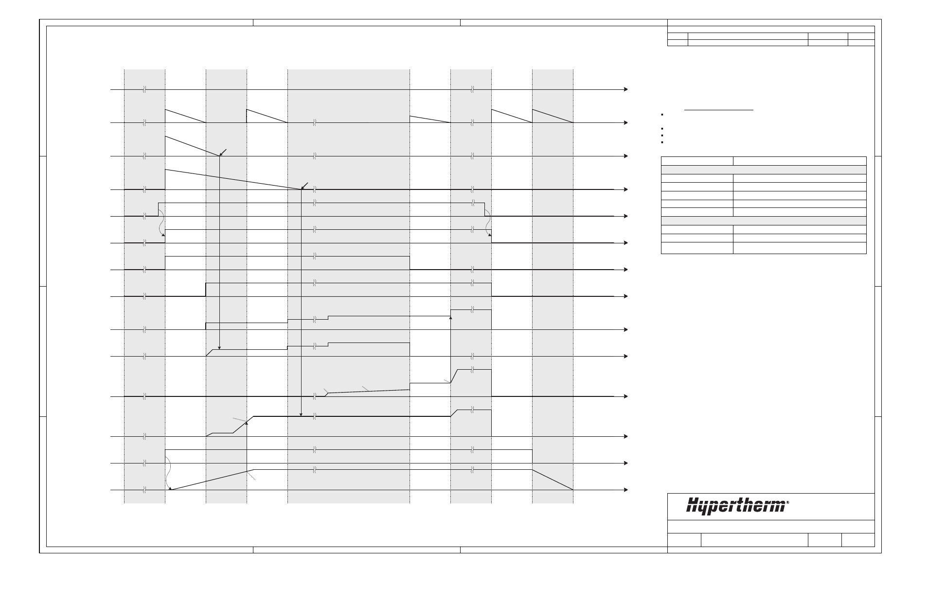
Start Switch
SEQ_State
IDLE
(0x0F)
Debounced
Start
Pilot Arc
Switch
Inverter
Enable
I
Command
I
Pilot
I
Work Lead
Arc
Voltage
Gas
Solenoid
Torch Gas
Pressure
SEQ_Timer
timer_TSC
5ms
2A/ms
GAS UP
(0x10)
T_PILOT_MIN
0.4A
T_GAS_UP
CUT
(0x40)
KNOB
POST FLOW
(0x60)
TORCH
RESET
(0x70)
IDLE
(0x0F)
8PSI
20s
T_TORCH_RESET
15A
15A
1.6A
2A/ms
PILOT
START
(0x20)
PILOT
(0x21)
KNOB
50V
TRANSFER
(0x30)
timer_TSO
T_TSO
Check TSO
T_TSC
Check TSC
INV ON
(0x11)
Torch gas ramping up delay
Description
Timeouts and Delays
Minimum pilot time delay
Delay from Gas Up to TSO test
Delay from Gas Up to TSC test
Torch consumable Reseat Time
Regular pilot current setting
Current Setpoints
Pilot current boost value
Assumptions:
This diagram represents most but not all possible State
transitions.
No Faults Occur.
System is not connected to a Load Bank.
System is running at Normal Mode at normal input line voltage.
Mnemonic
T_GAS_UP
T_PILOT_MIN
T_TSO
T_TSC
T_TORCH_RESET
pilot_current_set
I_PILOT_HIGH_DELTA
pilot_current_set
pilot_current_set
pilot_current_set +
I_PILOT_HIGH_DELTA
pilot_current_set +
I_PILOT_HIGH_DELTA
I_TRANSFER
I_TRANSFER
Transfer current = pilot_current_set
+ I_PILOT_HIGH_DELTA
I_TRANSFER
CUTTING FSM TIMGING DIAGRAM -NORMAL
Diagramma tempo di taglio pagina 1 di 2