Proel MATRIX88 Manuale d'uso
Pagina 29
29
11. Sensitivity selector
Position this selector on:
•
LINE if that input (LINE5÷LINE8) is connected to an external line level audio source
(CD player, MP3
player, DVD reader, etc.)
•
MIC if that input (LINE5÷LINE8) is connected to a dynamic microphone
•
PHANTOM (48 V DC) if that input (LINE5÷LINE8) is connected to a microphone that needs Phantom
power
12. PAGING MIC1 / MIC2
Connect the BM8X8 paging console to this input.
The system accepts up to two BM8X8 paging consoles (one per port).
Paging consoles have the same priority and cannot send an announcement simultaneously (even if to
different zones).
- As long as one channel is busy with one paging console, the other paging console cannot be used
- If the system includes several daisy-chained MATRIX88 units, you can only connect 2 BM8X8 paging
consoles to the PAGING MIC inputs on the Master unit. Those consoles will operate on the whole
system.
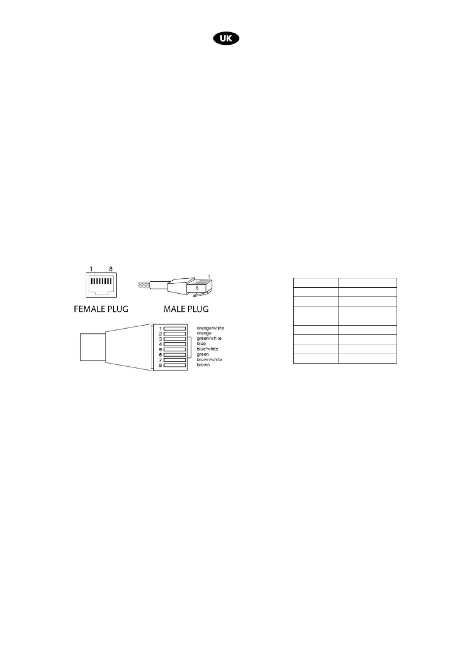
Pins on RJ45 port:
Connection between a UTP CAT5 cable and an RJ45 connector to link a microphone station, according to
the EIA/TIA – 568B standard:
13. GAIN PAGING MIC1 / MIC2
Adjusts the audio level of the respective BM8X8 paging console.
14. MICROPHONE 1 input
The MIC1 balanced XLR input has a 600 ohm impedance.
Each zone features a priority button for MIC1 (fig. 1, ref. 5). When the MIC1 priority button is not activated,
MIC1 will be mixed with the rest of the line inputs on each zone. On the contrary, when it is activated, MIC1
will have priority on all the other line inputs from 1 to 8 and L.
MIC1 level will be controlled by the MIC1 level knob (fig. 1, ref. 6), by the master level knob (fig. 1, ref. 8)
and by the MIC1 gain trimmer (fig. 2, ref. 15).
The MIC1 signal will be sent to all the Slave units connected to the system.
15. MlC1 Gain
Gain control adjusts the microphone input signal level (from 5 mV to 300 mV).
16. MIC1 Input Tone Control
LF adjusts low frequencies
HF adjusts high frequencies
Piedino N° Assegnazione
1
RS485 B
2
RS485 A
3
GND
4
+ 24 V (OUT)
5
GND
6
+ 24 V (OUT)
7
MIC IN +
8
MIC IN -