Fronius Symo x.x-3-S Manuale d'uso
Pagina 16
14
After cutting out because of overcurrent or undervoltage, the inverter attempts to restore
the power supply in the Fronius Solar Net every 5 seconds while the fault is still present.
Once the fault is rectified, power to the Fronius Solar Net will be restored within 5 seconds.
Example
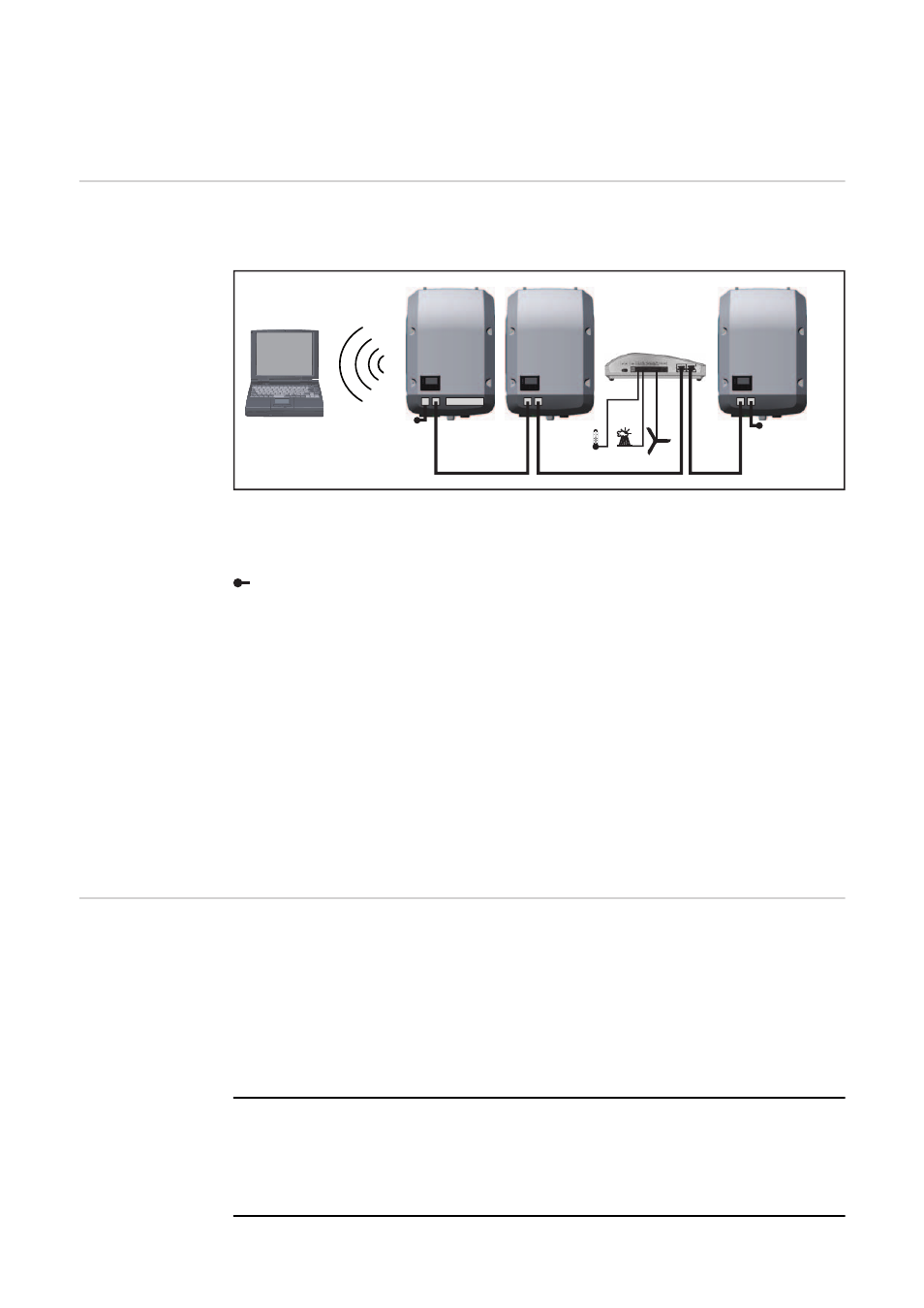
Recording and archiving data from the inverter and sensor using a Fronius Datamanager
and a Fronius Sensor Box:
Data network with 3 inverters and a Fronius Sensor Box:
- Inverter 1 with Fronius Datamanager
- Inverters 2 and 3 without Fronius Datamanager!
The external communication (Fronius Solar Net) takes place on the inverter via the data
communication area. The data communication area contains two RS 422 interfaces as in-
puts and outputs. RJ45 plug connectors are used to make the connection.
IMPORTANT! Since the Fronius Datamanager functions as a datalogger, the Fronius So-
lar Net ring must not include any other datalogger.
There must only be one Fronius Datamanager in each Fronius Solar Net ring.
Fronius Symo 3 - 10 kW: Any other Fronius Datamanagers must be removed and the un-
occupied option card slot sealed off using the blanking cover (42,0405,2020 - available
from Fronius as an optional extra); alternatively, use an inverter without Fronius Datama-
nager (light version).
Fronius Symo 10 - 20 kW, Fronius Eco: Any other Fronius Datamanagers must be re-
moved and the unoccupied option card slot sealed off by replacing the cover (item no.
42,0405,2094); alternatively, use an inverter without Fronius Datamanager (light version).
Explanation of
the multifunction
current interface
Various wiring variants can be connected to the multifunction current interface. However,
these cannot be operated simultaneously. For example, if an S0 meter is connected to the
multifunction current interface, it is not possible to connect a signal contact for overvoltage
protection (or vice versa).
Pin 1 = measurement input: max. 20 mA, 100 Ohm measurement resistor (load imped-
ance)
Pin 2 = max. short circuit current 15 mA, max. open circuit voltage 16 V DC or GND
Wiring diagram variant 1: Signal contact for overvoltage protection
Depending on the setting in the Basic menu, the DC OVP Typ 2 option (overvoltage pro-
tection) either outputs a warning or an error on the display. Further information on the DC
OVP Typ 2 option can be found in the installation instructions.
= Terminating plug
1
2
3
IN
OUT
°C
W/m²
m/s
IN
OUT
IN
OUT
Sensor Box
WLAN
* Fronius Datamanager
*
IN
OUT