Riello UPS MultiCOM 382 Manuale d'uso
Pagina 14
- ENGLISH -
14
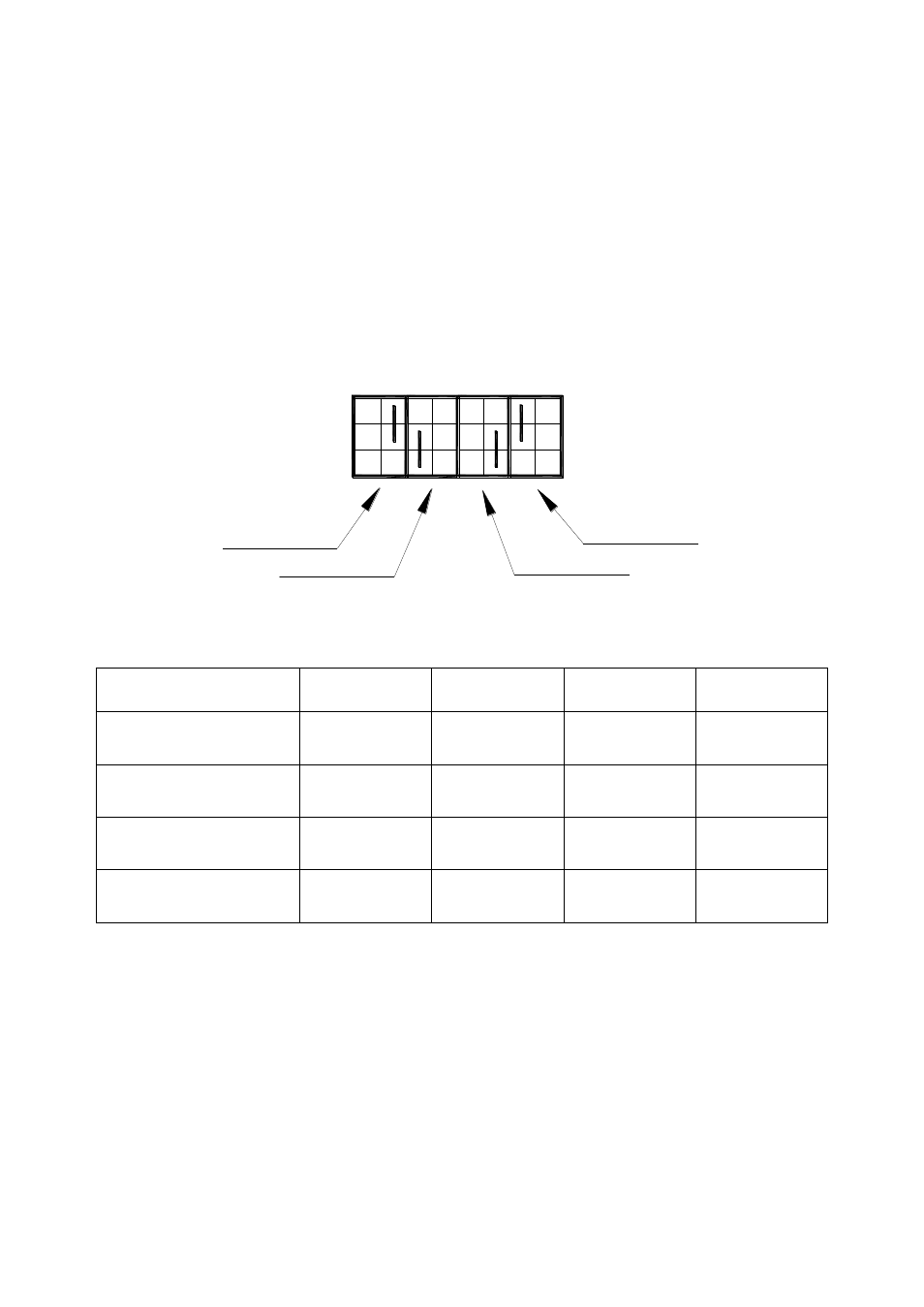
It is also possible to have the same signal associated with several contacts, as shown
in Table 1. This configuration is achieved by moving the straps on jumpers SW1
–
SW8. The default configuration of the jumpers is shown in Figure 3. Refer to Table 1 for
indications on how to modify the initial configuration.
E.g: to associate the “Battery Low” signal with relay RL1, insert the strap between
jumper 1 and jumper 2 in the SW2 column. N.B. In this case, column SW1 must be left
free.
Figure 3
Command
RL1(N.O.)
RL2(SC.)
RL3(N.O.)
RL4(SC.)
Battery Working
SW1(2-3)
SW3(2-3)
Default
SW5(2-3)
SW7(2-3)
Battery Low
SW2(1-2)
Default
SW4(1-2)
SW6(1-2)
SW8(1-2)
Alarm
SW2(2-3)
SW4(2-3)
SW6(2-3)
Default
SW8(2-3)
Bypass
SW1(1-2)
SW3(1-2)
SW5(1-2)
SW7(1-2)
Default
Table 1: Signal-relay association configuration
Warning: c
onfiguration jumpers must never be connected across adjacent SW’s
(referring to Figure 3, the jumpers must not be positioned horizontally). Moreover, the
same relay must not be associated with two different signals.
SW8
SW7
SW6
SW5
SW4
SW3
SW2
SW1
1
2
3
1
2
3
Sett. RL4
Sett. RL1
Sett. RL2
Sett. RL3