Riello UPS MultiCOM 382 Manuale d'uso
Pagina 13
- ENGLISH -
13
POWER SUPPLY OUTPUT
The J1 terminal board has a 12Vdc power supply that can be used by the user
provided no more than the 80mA available is drawn.
1
2
3
4
J1
12Vdc ±10%
max 80mA
+12V
GND
3 DESCRIPTION AND CONFIGURATION OF THE
CONTACTS PORT SECTION
CONFIGURATION OF THE CONTACTS PORT SECTION
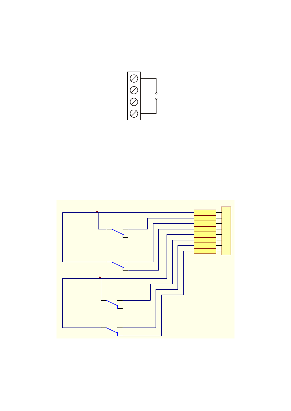
The Bypass, Battery Working, Battery Low and Alarm signals can be associated with
the four relays on the card (two with switchover contacts (SC) and two with an (N.O.)
contact).
1
2
3
4
5
6
A
B
C
D
6
5
4
3
2
1
D
C
B
A
Title
Number
Revis ion
Size
B
Date:
26-Apr-2004
Sheet of
File:
G:\evaldo\..\SCHEM AxM ANUALE.s ch
Drawn By:
RL2B
RL4B
RL3_NO
COM 1
RL4_NC
RL2_NO
COM 2
RL2_NC
RL1_NO
RL4_NO
RL3B
RL1B
8
7
6
5
4
3
2
1
J 3
Figure 2: Contacts on the internal relays and how they are connected to the connector