Optional multi-system interface – Hypertherm HPR260 Auto Gas Manuale d'uso
Pagina 223
7-24
120
RX
Termination
Termination
120
TX
4
3
2
1
1
A
4
3
2
A
B
C
D
B
C
D
Unit 1
Interface
CNC
(Customer Supplied)
041909
CONTROL BOARD
1 2 3 4
S100
1 2
J303
3 4
3
2
1
4
J300A
J300B
CNC Interface Cable
J300A
S100
J300B
J303
3
2
1
4 1
CONTROL BOARD
041909
2 3 4
Unit 2
J300A
S100
J300B
J303
3
2
1
4 1
CONTROL BOARD
041909
2 3 4
Unit 3
J300A
J300B
S100
J303
1 2 3 4 1
041909
CONTROL BOARD
4
3
2
Unit 4
CNC Interface Cable
CNC Interface Cable
CNC Interface Cable
Serial ID
Dipswitch
Machine Motion
Jumper Block
Jumper Block
Machine Motion
Dipswitch
Serial ID
Jumper Block
Machine Motion
Dipswitch
Serial ID
Jumper Block
Machine Motion
Dipswitch
Serial ID
J106
2
1
J107
1 2
J106
1 2
1 2
J107
J106
1 2
1 2
J107
J106
1 2
1 2
J107
Optional Multi-System Interface
1
3
2
4
3
1 2
4
1 2 3 4
5 6 7 8
1
3
2
4
7
5 6
8
6
5
7 8
HPR PAC
Dry Cutting System
HPR PAC
Dry Cutting System
HPR PAC
Dry Cutting System
HPR PAC
Dry Cutting System
D
18
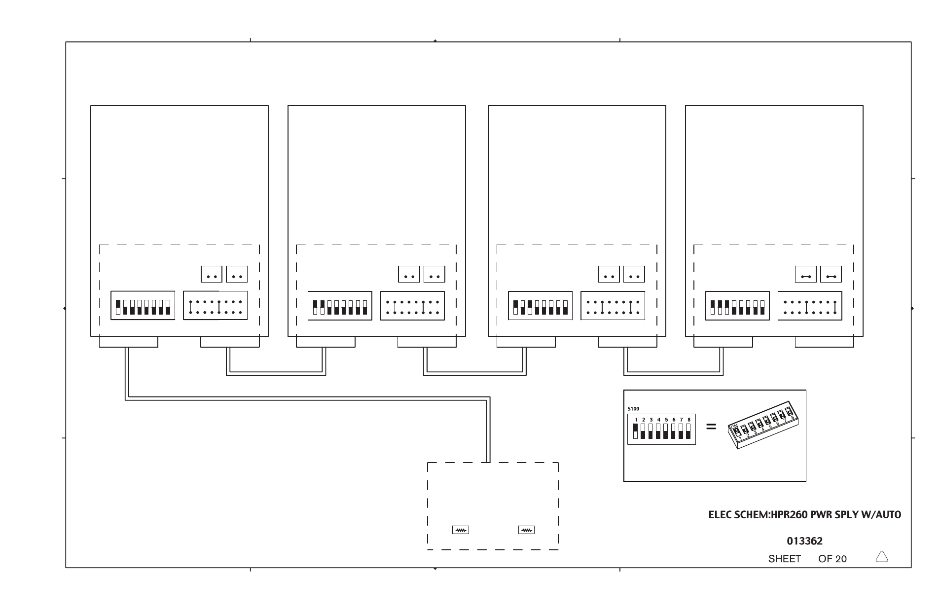
Notes:
1) For single system installations set Serial ID (S100), and Machine Motion (J303) as shown in Unit 1,
jumpers J106 and J107 must be closed
2) On multi-system installations refer to the illustration.
Jumpers J106 and J107 are left open on all systems except for the very last system where
they are in the closed position
Termination resistors (120-ohm) or termination jumpers must be installed/set at the CNC for
each of the RS-422 RX and TX signal pairs.
3) Use only the first four dipswitch settings, they are the same as on the 041808 control
board
5
Dipswitch setting example:
Switch 1 is in the ON position.
Switches 2-8 are in the OFF position.
*
*
* If a Hypertherm Automation controler is being used, and there are intermittent communication
failures (PS Link Failure), try removing the jumpers on J106 and J107 on the control board, and the
termination jumper (J6 or J8) on the serial isolation board in the controler. Only remove the
termination jumper on the serial isolation board that is connected to the HPR power supply. See
sheet 19 of 20 for more details.