Proel ZONE8 Manuale d'uso
Pagina 22
22
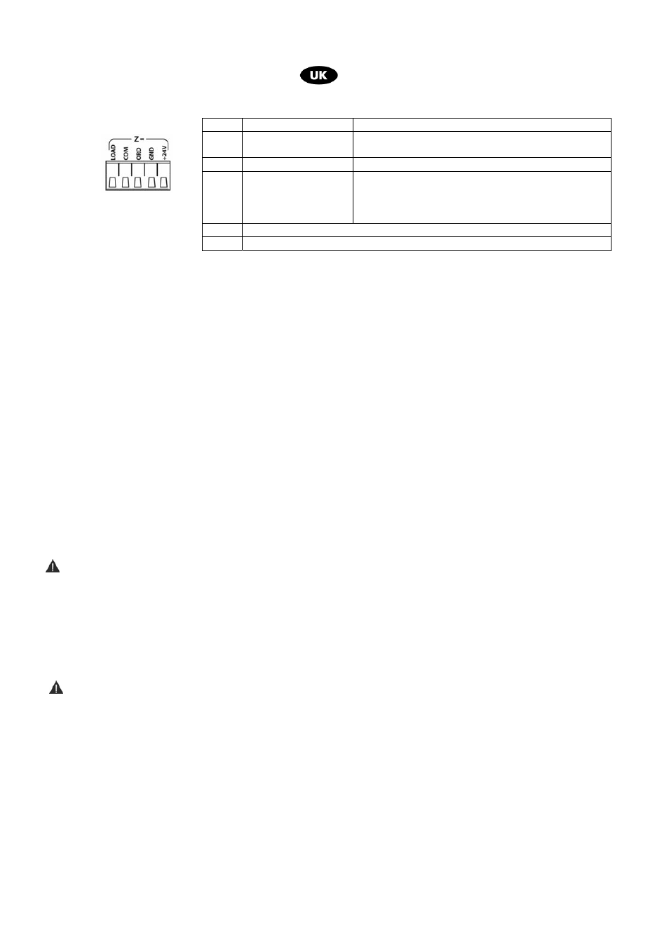
14 Terminal board for zones outputs
15 Emergency microphone input and Siren alarm key (Control N.O)
16 Connector for interconnection with external audio external matrix (MATRIX88)
17 Tone Chime level control (warning signal prior announcement )
18 Audio signal output ( voice/music mixed signal)
19 Connector for Audio signal interconnection with external ZONE8 extension unit
20 Audio/music signal output
21 Audio signal inputs for music background purposes
22 Audio signal output for log events recording purposes
23 Dip-switch for principal operating functions selection
24 RJ45 Connector for microphone call station inputs (microphone stands referred BM01-BM04-BM08)
25 RJ45 Connector for connection with external extension unit (Z8SLAVE unit)
26 Audio signal input with priority and VOX- central telephone input
6. INSTALLATION AND POWER SUPPLY
Warning:
Do not set the unit in ambient subject to vibration, to humidity or dust.
For connections ensure to contact authorized installer to avoid to damage the unit .
Ensure that the main power supply is in accordance with the unit specifications. Ensure to use an
earthed plug to connect the unit to main power source.
7. DC EMERGENCY POWER SUPPLLY
Warning
ZONE8 has been designed to operate in EMERGENCY with constant external voltage 24Vdc to be
applied to respective terminal boards ref.12-fig2.
NB- Led indicator on front panel ref.9-fig.1 lights when DC power supply level is under 19 VDC.
Note
A – For constant power supply voltage by batteries , the unit is not set to censure the batteries re-charge.
B – In case of the sole presence 24 Vdc power supply ( there is no main Vcc power supply) The
microphone call station set at a certain distance from the unit could not be operating. But if present and
installed the emergency call station microphone operating is assured.
A/B Configuration
C configuration
LOAD
Power signal
(100V)
”+” Line Signal
COM
Reference at 0V
”– ” Line reference
ORD
-
Normally at 0 V, In case of situation of
BY-PASS
Power Signal (100V)
( 3 wires system)
GND
Pole ”– ” BY-PASS Relay power supply
+24V
Polo ”+ ” BY-PASS Relay power supply