Proel AMP03VR Manuale d'uso
Pagina 21
21
6. INSTALLATION
1. Input connections
• MIC1 and MIC2 inputs (fig. 1, ref. 7) are 6.3 mm mono jacks and can be used to connect low impedance (30-
600 ) dynamic microphones. The MIC1 input features a VOX function that, when driven by a signal,
prioritizes it and excludes all other inputs: in this way only the audio signal present on the MIC1 input is
reproduced at the output.
• The AUX/PHONO input (fig. 2, ref. 4) is used to connect line level sound signal source (i.e. AM/FM tuner,
cassette player, CD player, etc.). The R and L RCA connectors allow the signal input of the right and left
channel respectively.
• Power Supply Cable
This supplies power to the unit (fig. 2, ref. 2).
Warning
Before you connect the unit to the mains outlet, make sure the power supply voltage selector (fig. 2, ref. 1)
matches the actual mains voltage.
2. Output connections
Beware!
To avoid the risk of electric shock do not touch the amplifier outputs when the amplifier is turned on.
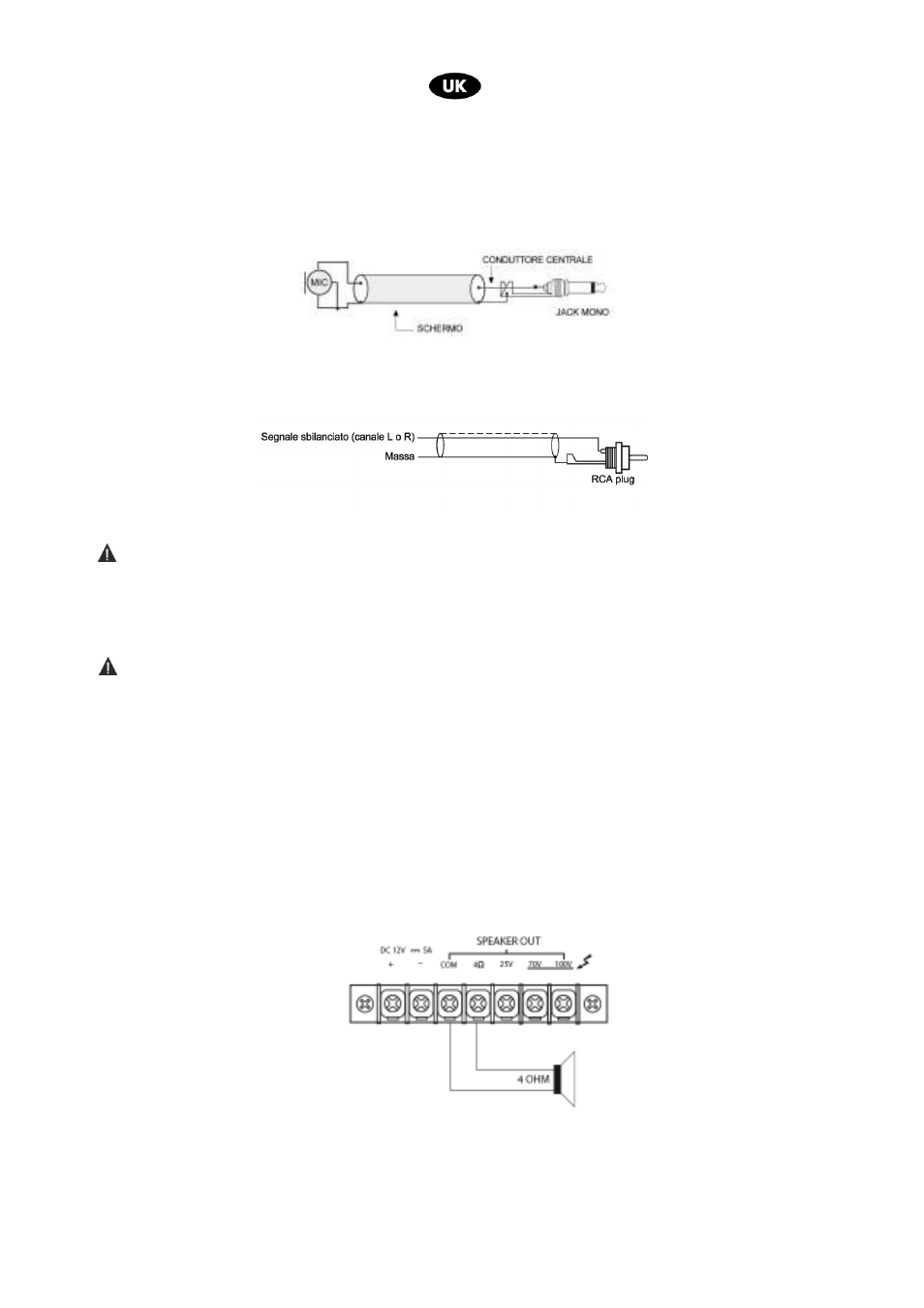
• Speaker connection
To access the speaker connectors (fig. 2, ref. 7) unscrew each respective screw terminal to remove the
protective cover.
The unit can be used both with constant impedance speakers (4 Ω) and with constant voltage speakers (25 V,
70 V, 100 V). Make the connections according to the following indications.
Constant impedance line
Connect one of the speaker line terminals to the COM terminal and the other to the 4 Ω terminal to get a
constant impedance line (4 Ω) .
−
−
−
− In order to get the maximum results, the total impedance of the speakers connected to the line has to
equal the amplifier output load impedance,
−
−
−
− The sum of the speakers power should not be lower than the amplifier output power.
−
−
−
− We advise keeping the connection cables as short as possible. In any case, the longer the cable is, the
larger its diameter should be.