Proel DWSKIT Manuale d'uso
Pagina 22
22
Channel A set up (Similarly for Channel C):
Press 2 times SET key (fig.1, ref.5) and set channel mode (CHANNEL/TUNE) through Arrow on “down” (fig.1,
ref.5) and press SET to confirm.
CHANNEL MODE: for each band 60 channels 250 Khz spaced are available.
TUNE MODE: for each band , 300 channels 50Khz spaced are available
The selection MODE does depend on the frequency occupancy status for each country and possible interferences
presence.
Press 3 times SET key and set Squelch level within -0,75dBm e -100dBm
Increasing the Squelch level we will increase the channel RX opening level therefore only signal above will be
received.
Increase such level in case of external interferences presence.
FREQUENCY OF USE AND MANUAL SET UP:
After having set CHANNEL or TUNE Mode press one time SET key, the operating frequency will start
lighting up, shift with the arrow “down” and “Up” (fig.1, ref.5) and set the frequency you want to use. Select one
stand amongst the four microphone stands operating in the same frequency range planned to be programmed
reading the indications reported on the back rear of this stand (fig.3, ref.11) and switch on.
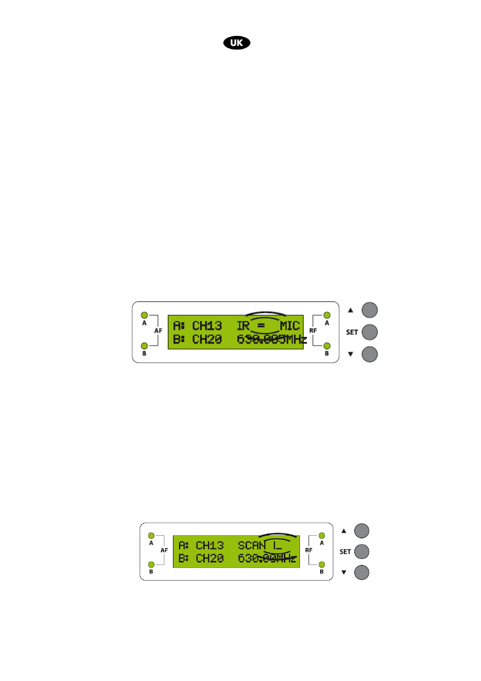
Position the stand to have the transmitter IR (fig.1, ref.7) and the receiver IR (fig.3, ref.5) are one front of the
other and press the Arrow “UP”, on the display will appear the following frame
When the microphone stand is coupled, the respective RF Led (fig.1, ref.4) will switch on and on the stand
display (fig.3, rif.7) the coupling frequency will appear. The stand of the Band A is programmed and ready to be
used.
AUTOMATIC SET UP OF THE FREQUENCY OF USE:
After having set CHANNEL OR TUNE Mode. Select one microphone stand within the four available
microphone stands operating in the same frequency planned to be programmed (reading the indications reported
on the rear back of this stand (fig.3, ref.11) and switch on.
Position the stand in order to have IR transmitter (fig.1, ref.7) and IR receiver IR (fig.3, ref.5) are the front one of
the other , press for 2 seconds Arrow key “UP” (fig.1, ref.5) . At this point on the display will appear the following
frame
The main central unit will scan the free frequencies and will appoint to the microphone stand the first free
available frequency .
When the microphone stand will be coupled and the relevant Led RF (fig.1, ref.4) will switch on, the same
frequency will appear on the microphone stand display.
At this point the stand of the Band A is programmed and ready for use.