Proel ZONE8SLAVE Manuale d'uso
Pagina 16
15
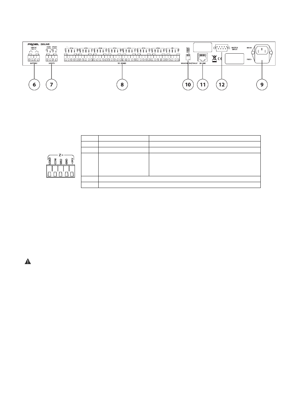
5. REAR PANEL
Fig.2
6. Terminal board for 24Vdc emergency power supply. Note: Use a protected power supply.
7. Voice/Music signal input terminal board.
8. Zone output terminal board.
9. Mains socket with built-in fuse holder.
10. DIP switch for main operating functions selection.
11. RJ45 connector for connection to ZONE8 main external unit.
12. Connector for connection to external audio matrix (MATRIX88).
6. INSTALLATION AND POWER SUPPLY
Warning
• Do not expose the unit to extreme humidity, dust, vibration and shock.
• Make sure connections are made by an authorized installer in order to avoid any damage to the unit.
• Check that the local power supply voltage corresponds to the value shown on the unit. Use grounded
plugs to connect the unit to the mains.
6.1 Connection to ZONE8 master system
To interface ZONE8 and Z8SLAVE correctly, interconnect the two RJ45 plugs (ref.11-fig2) using the CAT5
cable supplied.
Then connect electrically the two units by interconnecting the two negative pole terminals of the 24Vdc power
supply terminal boards (ref.6-fig2).
Configuration B
Configuration C
LOAD Power signal (100V)
”+” Line signal
COM
Reference at 0V
”–” line signal
ORD
-
Generally 0 V, in case of
BY--PASS
Power signal (100V)
(3-wire system)
GND
”–– ” Pole BYPASS relay power supply
+24V
”+ ” Pole BYPASS relay power supply