Greenheck PCO1000BAO PCOWeb (MSTP-RS485 Interface Board) Manuale d'uso
Attrezzatura Greenheck
CAREL code +050000930 - rel. 1.1 dated 25/07/06
pCOnet PCO1000BA0 - Scheda di interfaccia BACnet MS/TP per pCO / BACnet MS/TP interface board for pCO
Fig. 1
Fig. 2
Fig. 3
Fig. 4
Tool BACset - Fig. 7
La scheda opzionale pCOnet (codice PCO1000BA0) per controllori pCO Sistema permette il collegamento di un pCO* ad una rete di tipo BACnet
MS/TP (Master/Slave Token pass). La connessione RS485 è optoisolata rispetto al controllore pCO*. Nota: pCOnet non è compatibile con la serie
pCOB*. pCOnet è di tipo Master/Slave.
Installazione Figg. 2, 3, 5: per installare pCOnet nel controllore pCO*:
1.
Disinserire l’alimentazione pCO e togliere lo sportellino “Serial Card” del pCO* (Fig. 2);
2.
inserire pCOnet nel corrispondente connettore a pettine interno, assicurandosi che sia ben inserita e a contatto con i due appoggi del pCO*.
Poiché lo spazio è esiguo, l’inserimento di pCOnet e l’accoppiamento dei connettori può risultare difficoltoso: inserire pCOnet obliquamente
e farla poi ruotare fino a far combaciare i connettori;
3.
inserire gli opportuni ponticelli (per il significato si veda più avanti);
4.
inserire lo sportellino di chiusura fornito in dotazione a pCOnet.
Nota: se il dispositivo utilizzato per la lettura dei dati dalla rete 485 è connesso a terra e l’eventuale convertitore RS232-RS485 o la seriale RS485
dello stesso dispositivo hanno un isolamento funzionale minore di 2kV è necessario collegare il connettore G0 della scheda pCOx a terra. Non è
possibile installare la scheda a diretto contatto con il pannello metallico del quadro elettrico.
Significato dei ponticelli
All’interno dell’apertura frontale dello sportellino si trovano i ponticelli P1, P2, P3.
Con riferimento alla fig. 4:
- il ponticello P1 inserisce una resistenza da 510 ohm di polarizzazione tra la linea dati negativa (-) e il riferimento GND;
- il ponticello P2 inserisce una resistenza di terminazione da 120 ohm tra le due linee dati (+) e (-);
- il ponticello P3 inserisce una resistenza da 510 ohm di polarizzazione tra la linea dati positiva (+) e la tensione interna +5 Vdc.
Inserire tutti e tre i ponticelli sulla unità ad inizio rete e su quella a fine rete. Non inserire ponticelli sulle unità intermedie. Per rispettare le
normative europee EMC di prodotto, è necessario aggiungere al cavo di rete la ferrite in dotazione come illustrato in Fig. 5.
Fig. 5
Fig. 6
Uso
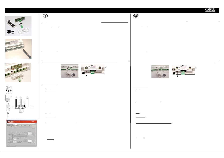
Con riferimento alla fig. 6:
Il LED Status (sinistra) indica lo stato della comunicazione con il controllore e anche lo stato di pCOnet.
Sequenza di avvio
: all’accensione, o dopo un riavvio di pCOnet, il LED Status esegue la seguente sequenza:
-spento per 2 secondi;
-dopo 2 secondi dal riavvio: rapido lampeggio rosso-verde-rosso-verde…;
-dopo 5 secondi dal riavvio: verde fisso;
-dopo circa 50 secondi dal riavvio: lampeggiante (colore lampeggio: vedi sotto - Stato della comunicazione con pCO*) inizia la
comunicazione pCOnet-pCO*.
Stato della comunicazione con pCO*: una volta conclusa la sequenza di avvio, il LED Status lampeggia per indicare la qualità della
comunicazione con pCO*:
-rapido verde-buio-verde se la comunicazione con pCO* è ok (pCO* ON-LINE);
-lento rosso-buio-rosso se la comunicazione con pCO* non è stabilita (pCO* OFF-LINE)
-verde-rosso-verde se pCOnet rileva errori o temporanea mancanza di risposta da pCO*.
Il LED RS485 (destra) indica lo stato della comunicazione con la rete BACnet MS/TP (485).
Il LED assume i seguenti stati:
Sequenza di avvio
: all’accensione o dopo un riavvio di pCOnet il LED RS485 esegue la seguente sequenza:
-spento per circa 50 secondi;
-dopo circa 50 secondi dal riavvio di pCOnet: verde–rosso–verde–rosso lentamente: al termine BACnet risulterà attivo.
Stato della comunicazione con rete BACnet MS/TP
: una volta conclusa la sequenza di avvio, il LED RS485 lampeggia per indicare la qualità
della comunicazione con la rete BACnet MS/TP:
-verde con occasionali lampeggi rossi se la comunicazione è ok (significato BACnet MS/TP: verde acceso = pCOnet detiene il Token
(controllo della rete MS/TP); verde spento = pCOnet NON detiene il Token; rosso acceso = Poll-For-Master, ricerca di un Master a cui poter
passare il Token);
-contemporaneo verde e rosso (significato BACnet MS/TP: Poll-For-Master continuo): comunicazione non stabilita (problemi di
connessione, o nessun dispositivo di rete trovato); questo potrebbe dipendere da difficoltà di connessione elettrica oppure da impostazioni
di comunicazione non compatibili con gli altri dispositivi di rete connessi. Si veda la sezione Configurazione.
Il tasto Pushbutton permette di :
- riavviare pCOnet
- richiamare la configurazione di fabbrica.
Riavvio di pCOnet
Da scheda accesa e a regime (quindi con LED Status regolarmente lampeggiante), tenere premuto il tasto per più di 5 s e per non più di 10 s.
The optional pCOnet board (code PCO1000BA0) for pCO sistema controllers allows the pCO* to be connected to a BACnet MS/TP network
(Master/Slave Token pass). The RS485 connection is optoisolated compared with pCO*. Note: pCOnet is not compatible with the pCOB* series.
pCOnet features Master/Slave operation.
Installation Figs. 2, 3, 5: to install pCOnet in the pCO* controller:
1.
Disconnect the power supply from the pCO* and remove the “Serial Card” cover (Fig. 2);
2.
insert pCOnet in the plug-in connector, making sure that it is fully inserted and in contact with the two supports on the pCO*. As there is
little space available, this operation may be complex: as a result, insert the pCOnet at an angle and then tilt it back until the connectors
line up;
3.
insert the required jumpers (see below for the meanings of these);
4.
fit the cover supplied with the pCOnet.
Nota: if the device used to read the data from the 485 network is earthed and the RS232-RS485 converter or the RS485 serial port on the device
have functional insulation of less than 2kV, connector G0 on the pCOx board must be earthed. The board cannot be installed in direct contact
with the metal panel on the electrical panel.
Meaning of the jumpers
Jumpers P1, P2 and P3 are located inside the front opening of the cover.
With reference to Fig. 4:
- jumper P1 adds a 510 ohm polarisation resistance between the negative data line (-) and GND;
- jumper P2 adds a 120 ohm terminal resistance between the two data lines (+) and (-);
- jumper P3 adds a 510 ohm polarisation resistance between the positive data line (+) and the +5 Vdc internal voltage.
Insert all three jumpers on the unit at the start of network and the unit at the end of the network. Do not insert the jumpers on the intermediate
units. For compliance of the product with the European EMC standards, add the ferrite supplied to the network cable, as illustrated in Fig. 5.
Fig. 5
Fig. 6
Operation
With reference to Fig. 6:
The Status LED (left) indicates the status of communication with the controller and the status of the pCOnet.
Starting sequence: on power-up, or after restarting pCOnet, the Status LED switches in the following sequence:
-OFF for 2 seconds;
-2 seconds after restarting: quick flash red-green-red-green…;
-5 seconds after restarting: green on steady;
-around 50 seconds after restarting: flashing (colour: see below - Status of communication with the pCO*) pCOnet-pCO* communication
starts.
Status of communication with the pCO*: once the starting sequence has been completed, the Status LED flashes to indicate the quality of
communication with the pCO*:
-quick green-OFF-green if communication with the pCO* is OK (pCO* ON-LINE);
-slow red-OFF-red if communication has not been established with the pCO* (pCO* OFF-LINE)
-green-red-green if pCOnet detects errors or a temporary lack of response from the pCO*.
The RS485 LED (right) indicates the status of communication with the BACnet MS/TP network (RS485).
The LED shows the following information:
Starting sequence: on power-up or after rebooting pCOnet, the RS485 LED switches in the following sequence:
-off for around 50 seconds;
-around 50 seconds after restarting pCOnet: slow green–red–green–red: at the end, BACnet will be active.
Status of communication with the BACnet MS/TP network: once the starting sequence has been completed, the RS485 LED flashes to
indicate the quality of communication with the BACnet MS/TP network:
-green with occasional red flashes if communication is OK (BACnet MS/TP meaning: green ON = pCOnet keeps the Token (control of the
MS/TP network); green OFF = pCOnet DOES NOT keep the Token; red on = Poll-For-Master, search for a Master to pass the Token to);
-green and red ON together (BACnet MS/TP meaning: continuous Poll-For-Master): communication not established (connection problems,
or no network device found); this may depend on electrical connection difficulties or communication settings that are not compatible with
the other network devices connected. See the section on Configuration.
The Pushbutton is used to :
- restart pCOnet
- recall the factory configuration.
Restarting pCOnet
With the board on and in stable operation (Status LED flashing continuously), hold the button for more than 5 seconds and no more than
10 seconds.
Pushbutton
RS485 LED
Pushbutton
RS485 LED
Status LED