Greenheck PCO20000F0 (Lonworks Interface Board) Manuale d'uso
Scheda seriale lonworks, Per pco, Lonworks
GB
Vi ringraziamo per la scelta fatta, sicuri che sarete soddisfatti del vostro
acquisto.
Le schede opzionali PCO20000F0, PCO20000R0, PCO10000F0 e PCO10000R0
dei controllori elettronici pCO
2
/pCO
1
permettono l'interfacciamento di questi ultimi
ad una rete LonWorks
®
.
Le schede PCO2* vanno utilizzate esclusivamente per il controllo pCO
2
e le
schede PCO1* solo per il controllo pCO
1
.
Avvertenza: per essere operative, le schede di interfaccia devono essere
programmate in funzione dell’applicativo installato sul pCO
2
/pCO
1
.
Le informazioni sulle modalità di programmazione della scheda sono contenute nel
manuale cod. +030221960.
Il programma risiede sulla memoria flash alloggiata su zoccolo, e la sua
programmazione può avvenire direttamente via rete LonWorks
®
, utilizzando
strumenti di installazione e manutenzione della rete, come ad es. LonMaker™.
Le schede si differenziano per il tipo di interfaccia lato rete LonWorks
®
e per il tipo
di controllore elettronico sul quale possono essere montate:
PCO*0000F0 - interfaccia con FTT-10A 78 kbs (TP/FT-10);
PCO*0000R0 - interfaccia con RS485 39 kbs (TP/485-39).
Il baud rate del pCO
2
/pCO
1
deve essere impostato a 4800.
L’indirizzo del pCO
2
/pCO
1
non è rilevante in quanto viene automaticamente
riconosciuto dalla scheda.
Montaggio
Con riferimento alle Figg. 1-4, il collegamento al pCO
2
/pCO
1
si ottiene a macchina
non alimentata secondo questa procedura:
1. Con un cacciavite, togliere lo sportellino "serial card" del controllore
elettronico (vedi Fig. 1);
2. Con un tronchesino, eliminare dallo sportellino la parte plastica prefratturata,
ottenendo il foro corrispondente all'uscita del connettore a 3 vie (vedi Fig. 2);
3. Inserire la scheda opzionale nel corrispondente connettore a pettine,
assicurandosi che la scheda sia ben inserita e a contatto dei due appoggi posti
sul contenitore del pCO
2
/pCO
1
(vedi Fig. 3).
Attenzione! L’inserimento della scheda e l’accoppiamento dei connettori
potrebbero risultare difficoltosi a causa dello spazio esiguo e dei due
appoggi plastici. Si consiglia l’inserimento obliquo della scheda e la sua
rotazione fino a far combaciare i connettori.
4. Richiudere lo sportellino facendo combaciare il connettore della scheda seriale
con il foro eseguito sullo sportellino (vedi Fig. 4).
Thank you for your choice. We trust you will be satisfied with your
purchase.
The optional PCO20000F0, PCO20000R0, PCO10000F0 and PCO10000R0 cards
for the pCO
2
/pCO
1
electronic controllers allow the latter to interface to LonWorks
®
network.
The PCO2* cards are used exclusively for pCO
2
controller and the PCO1*
cards only for pCO
1
controller.
Warning: to be ready for use, the cards must be programmed in accordance the
application program installed on the pCO
2
/pCO
1
.
For the programming procedure of the card read the installation manual code
+030221960.
The program is installed on the flash memory placed on the socket and it can be
programmed directly via LonWorks
®
network, using the network installation and
maintenance tools like LonMaker™.
The cards differ in the type of interface on the LonWorks® network side and in the
electronic controller type on which they can be mounted:
PCO*0000F0 - interface with FTT-10A 78 kbs (TP/FT-10);
PCO*0000R0 - interface with RS485 39 kbs (TP/485-39).
The baud rate on the pCO
2
/pCO
1
must be set at 4800.
The address of the pCO
2
/pCO
1
is not important, as it is automatically recognised
by the card.
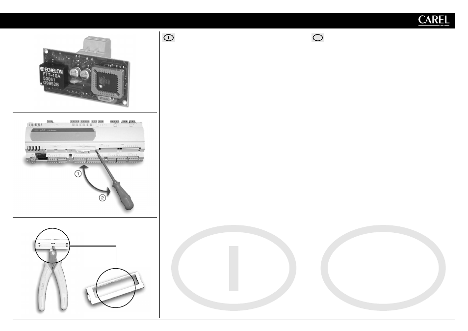
Connections
With reference to Figs. 1÷4, the connection to the pCO
2
/pCO
1
is performed (without
power supply) by following the procedure below:
1. Using a screwdriver, remove the "serial card" hatch from the electronic
controller (see Fig. 1);
2. Using cutting nippers, remove the pre-cut plastic part of the hatch, making
the hole for the 3-way connector (see Fig. 2);
3. Insert the optional board in the corresponding plug-in connector, making
sure that the board is properly fitted and rests against the two plastic
supports on the pCO
2
/pCO
1
case (see Fig. 3).
Attention! The insertion of the card and the fitting of the connectors may
be difficult due to the space available and the presence of the two plastic
supports. The board should be inserted obliquely, and then rotated until
the connectors are fitted.
4. Close the hatch, lining up the connector on the serial board with the hole made
in the hatch (see Fig. 4).
cod. +050004040 rel. 3.0 - 24.02.03
PCO20000F0 - PCO20000R0 - PCO10000F0 - PCO10000R0
Scheda seriale LonWorks
®
per pCO
2
/pCO
1
/ LonWorks
®
serial card for pCO
2
/pCO
1
GB
Fig. 1
Fig. 2
Apertura sportellino/Removal hatch
Eliminazione parte prefatturata/Removal pre-cut plastic part