Proel ZONE8 Manuale d'uso
Pagina 25
25
9. CONNECTIONS
9.1 Inputs
9.1.1 AUX1-AUX2-TUNER-CD-TAPE – Music sources Auxiliary inputs
The available music sources must be connected respectively to RCA inputs , the further RCA input referred
“REC” is set for eventual total log event external recording purposes. Such signal inputs are to be selected
respectively throughout the input commutator ref.2-fig1, level set by volume control ref.3-fig1 and sent to
the different eight zones throughout the relevant keys ref.5-fig1.
9.1.2 VOX/AUX-MESSAGE-TELEPHONE – VOX –Inputs with priority levels
3 high level audio inputs are available and are priority VOX
function equipped (ref.26-fig.2). Such 3 inputs with similar
sensibility levels can be set for different use. The
respective gain control allows the correct adjustment for
available signal in input.
The following figure is referring only to VOX/Telephone
inputs
9.1.3 BASES INPUTS – Call station microphones inputs
On the unit rear panel N° 6 RJ45 inputs are available to be used for Zone8 BM08/BM04/BM01 microphone
stand connection throughout CAT5 cable, On each of these 6 inputs it is possible to connect in cascade
N°. 3 call station microphones for a total of N° 18 microphone stands.
NB – The microphone stands present and involved by the configuration are directly power supplied by
ZONE8 unit.
But for lengths over than 200/250 meters there could be some excessive power level decrease visualized
by Low Mains led Indicator. Led set rear BMO1-BM04-BM08 microphone call stations. In this case the
local call microphone station power supply purposes are necessary throughout the optional
( to be purchased separately ) power supply unit BMPWS ((230VAC/12V~ – 500mA ).
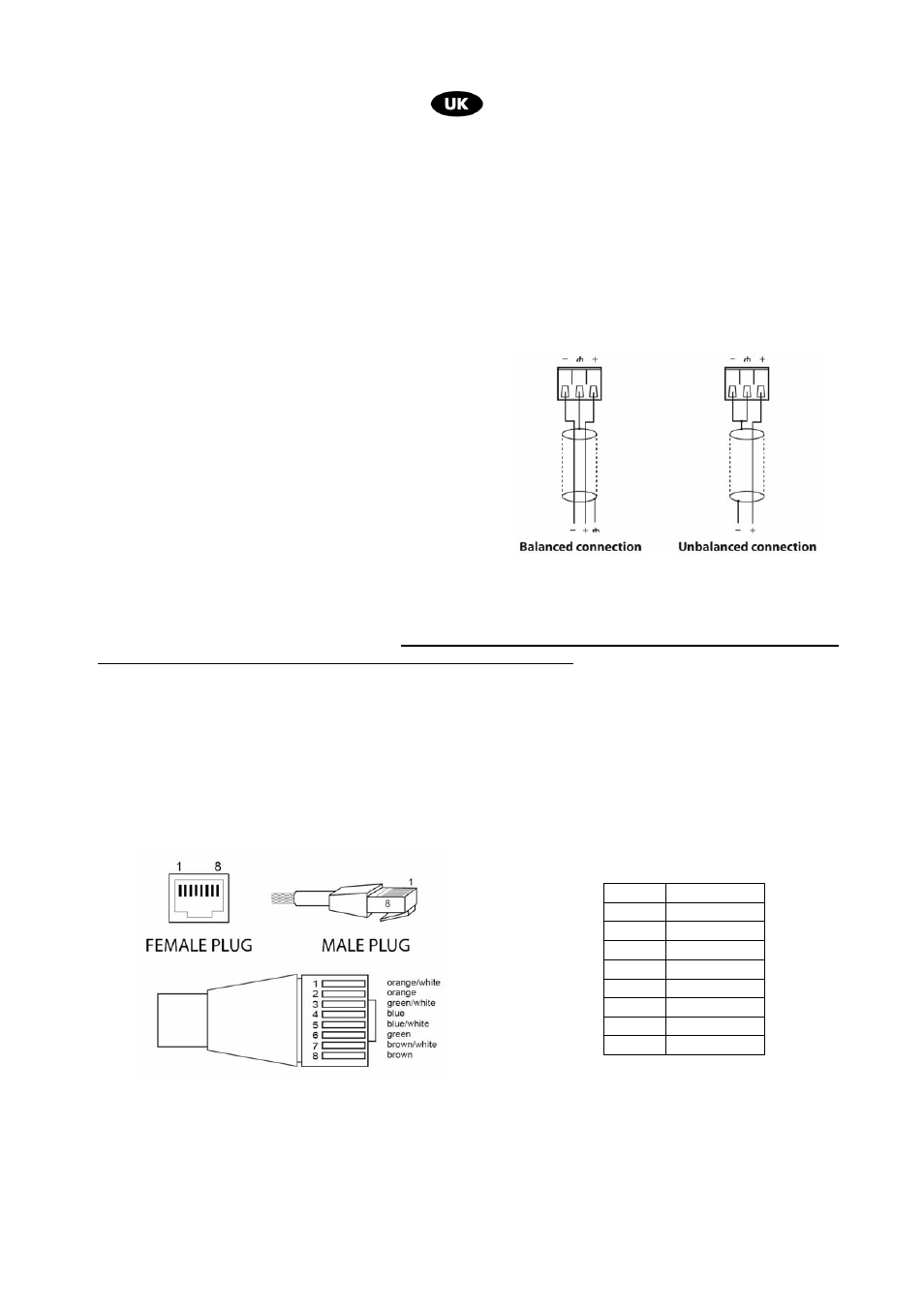
UTP CAT5 cable and RJ45 connector details for call microphone station connections in accordance with
EIA/TIA – 568B standards
9.1.4 EMERGENCY MIC – Microphone input and Emergency Siren key (ref.15-fig.2)
Using the accessory microphone referred ZONEFIRE –connected as per the scheme herein- an alarm
message in general call or in priority purposes can be diffused to the different zones of the installation.
Such function is activated automatically pressing lateral microphone body key.
Pin N° Assignment
1
Data “+”
2
Data “-“
3
+15V
4
+15V
5
+15V
6
GND
7
GND
8
GND