Rear panel – RCF UP 2161 Power Amplifier (160W) Manuale d'uso
Pagina 7
ENGLISH
0
d
B =
signal
level
that
allows
to
get
the
amplifier
maximum
power
.
t
he
internal
‘
limiter
’
circuit
helps
to
avoid
the
amplifier
overloading
,
yet
it
is
advisaBle
to
reduce
the
master
volume
when
the
sig/pK led
is
continuously
indicating
red
.
3
Main
POWER
switch (0 = off; I = on)
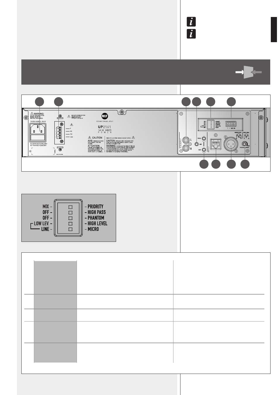
REAR
PANEL
4
MAIN INPUT settings through 5 dip-switches:
1
MIX – PRIORITY
MIX: the priority function is disabled
(the AUX INPUT is always open, even if the priority
command has been activated).
PRIORITY: the MAIN INPUT has priority over the
AUX INPUT when either the command has been
activated (CMD linked to GND on the removable
connector) or priority is taken from a paging
microphone connected to the RJ 45 port.
2
OFF – HIGH PASS
OFF: the audio hi-pass filter is not inserted (flat
frequency response).
HIGH PASS: the audio hi-pass filter is inserted.
3
OFF – PHANTOM
OFF: the PHANTOM power supply is disabled.
PHANTOM: the PHANTOM power supply is
enabled.
4
LOW LEV.
HIGH LEVEL
LOW LEVEL: the MAIN INPUT level is selectable
through the dip-switch no.5 between LINE
(– 20 dBu) and MIC.
HIGH LEVEL: the MAIN INPUT level is set to 0 dBu.
5
LINE – MICRO
LINE: the MAIN INPUT level is set to LINE
(– 20 dBu).
MICRO: the MAIN INPUT level is set to MIC.
4
5
8
7
6
9
10
11
12
13