Proel AUP4125S Manuale d'uso
Pagina 19
19
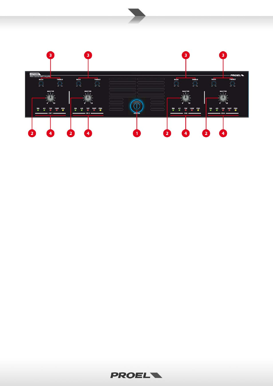
3. FRONT PANEL CONTROLS AND FUNCTIONS
fig.1
1. POWER
Main switch with indicator light turned on
2.
MASTER
Master volume control of the relative channels
3.
TREBLE and BASS
Low and High pitch control of the relative channels
4.
Status indicator
For each channel:
SIG: Green LED On indicates there is an input signal
4Ω: Green LED On ‐ channel set to operate with 4Ω
Connect loads having minimum electrical impedance of not less than 4Ω to the output terminal (Fig. 2,
Ref. 8)
70V: Red LED On ‐ channel set to operate with 70V
Connect loads of 70V to the output terminal (Fig. 2, Ref.8)
100V: Red LED On ‐ channel set to operate with 100V
Connect loads of 100V to the output terminal (Fig. 2, Ref.8)
PRO: Orange LED On ‐ channel Protected
Should a channel go into protection mode, check that the output load matches the features of the
amplifier and/or reduce the input signal level.