Proel ACDT180 Manuale d'uso
Pagina 19
19
5. Led Level indicator - Vu meter
It indicates the output signal level . For a correct amplifier volume use, the volume level must be set
between –20 dB e 0 dB and when the first five leds are on. If such level makes lighting only the first 2
leds (+3 dB +6 dB), the output signal could be distorted the volume then must be reduced.
6. Digital Radio Module
7. ON/OFF Switch for Radio Section
8. Radio volume control
9. CD/MP3 player module
10. CD housing
11. USB Input
12. Brackets for 19” rack housing purposes”
13. Handle
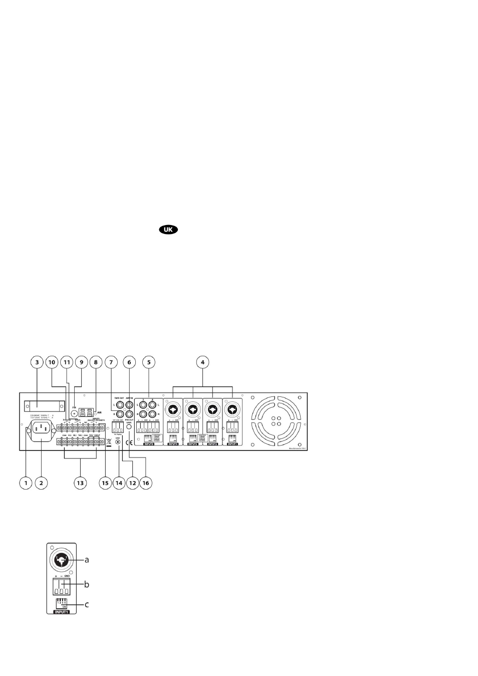
3. REAR PANEL CONTROL
fig. 2
1. Main Power supply plug ( with fuse)
2. Protection Fuse
It protects the unit against eventual power supply voltage variation. It can be replaced .
3. Main power supply voltage selector 230/117Vca 50/60Hz
4. Inputs INPUT1 ~ INPUT4:
a. COMBO/XLR Input connector
b. Euro block terminal – can be removed
c. Dip-switch:
PIN1 position ON=Input for a signal- Micro level
position OFF=input for a signal-.LINE level
PIN2 position ON = Input direction is inverted
PIN3 position ON = High pass filter – active in input (ideal for speech)
position OFF = on input no filter action
PIN4 position ON = Phantom 48V active
position OFF = Phantom 48V not active
When INPUT1 is active , the unit makes in Mute status all other signal sources