RISCO Group Wireless IR Beam IR Beam 74 Manuale d'uso
Wireless ir beam, Model: ir beam 74 modello: ir beam 74, 1 2 34 o n
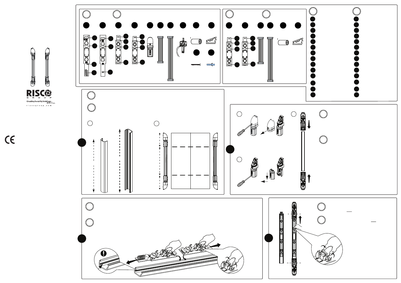
Cut the rail and the IR filter to the required size. Note the following:
A. The length of the IR filter cover should be shorter by 2 cm from the aluminum rail.
B. The length of a rail holder is 12 cm (each side) when attached to the rail.
H
12cm
12cm
IR filter cover
Coperchio/filtro IR
Main kit
Extension kit
IR aluminum rail
Barriera in alluminio IR
Tx
Rx
Wireless IR Beam
Model: IR Beam 74
Modello: IR Beam 74
Assembly Instructions
Istruzioni per l’assemblaggio
© RISCO Group 05/2010
5IN1384 B
Tx Rail Rx Rail
RISCO Group Limited Warranty
RISCO Group and its subsidiaries and affiliates ("Seller")
warrants its products to be free from defects in materials
and workmanship under normal use for 24 months from the
date of production. Because Seller does not install or
connect the product and because the product may be used
in conjunction with products not manufactured by the
Seller, Seller cannot guarantee the performance of the
security system which uses this product. Seller's obligation
and liability under this warranty is expressly limited to
repairing and replacing, at Seller's option, within a
reasonable time after the date of delivery, any product not
meeting the specifications. Seller makes no other warranty,
expressed or implied, and makes no warranty of
merchantability or of fitness for any particular purpose.
In no case shall seller be liable for any consequential or
incidental damages for breach of this or any other
warranty, expressed or implied, or upon any other basis of
liability whatsoever.
Seller's obligation under this warranty shall not include any
transportation charges or costs of installation or any liability
for direct, indirect, or consequential damages or delay.
Seller does not represent that its product may not be
compromised or circumvented; that the product will prevent
any personal injury or property loss by burglary, robbery,
fire or otherwise; or that the product will in all cases provide
adequate warning or protection. Buyer understands that a
properly installed and maintained alarm may only reduce
the risk of burglary, robbery or fire without warning, but is
not insurance or a guaranty that such event will not occur
or that there will be no personal injury or property loss as a
result thereof.
Consequently seller shall have no liability for any personal
injury, property damage or loss based on a claim that the
product fails to give warning. However, if seller is held
liable, whether directly or indirectly, for any loss or damage
arising under this limited warranty or otherwise, regardless
of cause or origin, seller's maximum liability shall not
exceed the purchase price of the product, which shall be
complete and exclusive remedy against seller.
No employee or representative of Seller is authorized to
change this warranty in any way or grant any other
warranty.
WARNING: This product should be tested at least once a
week.
All rights reserved. No part of this document
may be reproduced in any form without prior
written permission from the publisher.
RTTE Compliance Statement
Risco Ltd. hereby declares that this equipment is in
compliance with the essential requirements and other
relevant provisions of Directive 1999/5/EC. For the CE
Declaration of Conformity please refer to our website:
www.riscogroup.com
H-2cm
H
x4
E
x2
F
x2
G
x4
F
x4
G
x4
H
x2
J
x2
J
+
x2
I
+
x2
I
A
B
Press the PCB Spring Lockers on the Rx and Tx
master units and slide them towards the rail
holders to the end of the rail.
Premere la molla di blocco dei moduli master
Rx e Tx e farli scorrere verso la fine della barriera
di alluminio.
Place the Rx master and Rx slave units into one aluminum rail and the Tx master and Tx slave units into the second rail.
Important: 1. Pay attention to the units direction as indicated in the drawings.
2. Pay attention that the units are correctly placed on the sliding track.
3. Make sure that the Rx and Tx master units are placed near the rail holders with the Rx/Tx stickers.
Posizionare i moduli Rx master e Rx slave in una delle barriere di alluminio e i moduli Tx master e Tx slave nell’altra.
Importante: 1. Prestare attenzione alla direzione dei moduli che devono essere posizionati come da figura in basso.
2. Prestare attenzione affinché i moduli siano correttamente inseriti nelle guide scorrevoli.
3.
Assicurarsi che I moduli master Tx e Rx siano posizionati vicino ai supporti/snodi con le etichette Rx/Tx
.
Place the rail holders on the top and bottom of
both the Rx and Tx aluminum rails as follows:
A. Take the rail holder and remove the tamper
cover (2A)
B. Remove the swivel cover (2B)
C. Slide the rail holder into the rail (2C)
Posizionare i supporti/snodi barriera nella parte
superiore ed inferiore della stessa per entrambi
le barriere TX e RX come segue:
A. Prendere il supporto/snodo e rimuoverne il
coperchio supporto (2A)
B. Rimuovere anche il coperchio dello
snodo (2B)
C. Far scorrere il supporto/snodo sulla
barriera (2C)
T AMPER
+
I
R X
x1
C
T AMPER
+
I
T X
x1
D
x1
B
x1
T AMPER
+
I
R X
x2
D
T AMPER
+
I
T X
x2
C
A
C
B
Tagliare la barriera in alluminio e il coperchio/filtro IR alla misura richiesta. Notare:
A. La lunghezza del coperchio/filtro deve essere minore di 2 cm rispetto alla barriera in
alluminio.
B. La lunghezza del supporto/snodo di chiusura della barriera è di 12 cm (per ogni lato)
quando racchiude la barriera.
EN
EN
IT
EN
IT
EN
IT
EN
IT
IT
1
3
2
4
A
4
4
3
2
2
3
1
3
2
4
4
3
2
4
4
Antenna in Receiver
Beam
Wall Tamper Connector
PCB Spring Locker
Flat Cable Connector
RC (Rx Master)
TC (Tx Master)
TX (Slave)
RX (Slave)
Rail holder
Tamper Kit
Battery
Flat Cable 35 cm
Flat Cable 65 cm
Flat cable holder
A
B
C
D
E
F
G
H
I
J
1
2
3
4
Antenna della barriera RX
Connettore tamper
antirimozione
Molla di blocco modulo IR
Connettore cavo piatto
RC (Master Rx)
TC (Master Tx)
TX (Slave)
RX (Slave)
Supporto/Snodo barriera
Kit tamper
Batteria
Cavo piatto 35 cm
Cavo piatto 65 cm
Supporto cavo piatto
A
B
C
D
E
F
G
H
I
J
1
2
3
4
3
2
4
4
3
2
4
4
II
K
L
x4
x4
EN
IT
Kit principale
EN
IT
Kit aggiuntivo
1 2 34
O N
RC
+
I
TC
1 2 3 4
O N
TAM PER
I
+