Crydom CMR Series Manuale d'uso
Cmr series, Removal from din rail, Mounting to the din rail
CMR Series
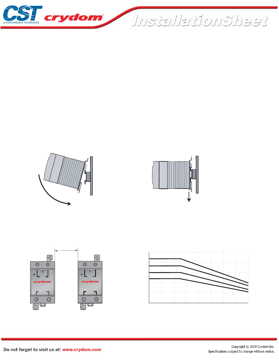
REMOVAL FROM DIN RAIL
To achieve maximum ratings, there must be
a minimum spacing of 1.6 inch (40mm)
between the devices in free air.
CMR Series SSRs are designed to fit to an industry standard TS35 DIN Rail. Mounting clip incorporates tabs for screw mounting to panel.
(40mm)
Minimum
60
45
75
30
15
20
40
60
80
AMBIENT TEMPERATURE (°C)
OUTPUT CURRENT (Arms)
Load Current vs Ambient Temperature
(100 % Duty Cycle)
MOUNTING TO THE DIN RAIL
Locate rail and align with non moveable
end of CMR DIN clip Using reasonable
force, push CMR in the direction of the
arrow shown.
The CMR power switching range is based on semiconductor
technology and therefore generates heat during operation.
The following deating curves must be observed before installation.
Crydom products are rated for 100% Duty Cycle.
Pull release tag in direction of arrow using
blade of screwdriver.
MOUNTING CONSIDERATIONS
THERMAL CONSIDERATIONS
MOUNTING OF CMR SERIES OF SOLID STATE RELAYS
OUTPUT
INPUT
IN
P
U
T S T A
T
U
S
OUTPUT
INPUT
IN
P
U
T S T A
T
U
S
_
_
_
_
_
_
_
_
_
_
_
_
_
_
_
_
0
CMR 65Amp
CMR 55Amp
CMR 45Amp
CMR 35Amp
1.6 inch
CMRINST
Rev. 081508
PAGE 1 OF 3
Crydoms CMR Series Solid State Relays were developed to offer the advantages of semiconductor switching technology in a
compact, self contained package. Quick and easy installation is coupled with low drive power requirements and efficient,
reliable power SCR output. Box Clamp terminals and LED status indication complete the package. This compact new design
offers up to 65Arms in ambient temperatures of 25°C.
Manufactured in Crydom’s ISO 9001 Certified facility for optimum product performance and reliability.
APPROVALS: UL, CSA, VDE, CE Mark.