Schema dei collegamenti – BECKHOFF M1410 Manuale d'uso
Pagina 11
M1410 Ingresso / uscita parellelo
Sistema II/O Lightbus Beckhoff
Data: 12.7.95
Versione : 2.0
pagina 11 di 13
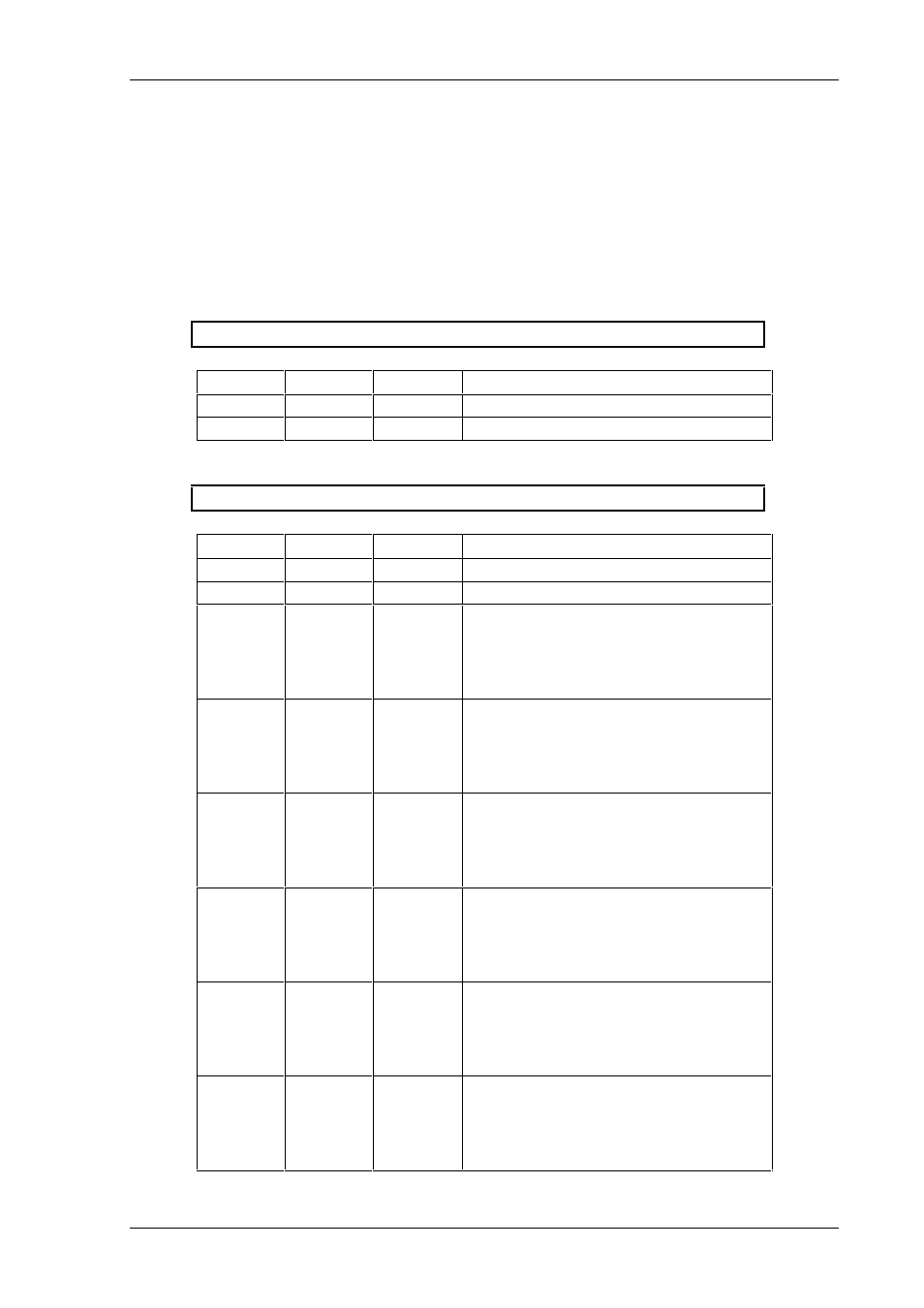
5. Schema dei collegamenti
Assegnazione del collegamento a spina con descrizione dei segnali
SPINA X10
Spina
Pin
Segnale
Descrizione
X10
1
+U
Tensione di comando +24V
X10
2
-U
Massa
SPINA X20
Spina
Pin
Segnale
Descrizione
X20
1
+A
+24V, alimentazione per uscite
X20
2
+A
+24V, alimentazione per uscite
X20
3
D0.0
Bit 0 del byte dati 0
D0.0 è uscita,
quando l’interruttore DIL S1 = ON
D0.0 è ingresso,
quando l’interruttore DIL S1 = OFF
X20
4
D0.1
Bit 1 del byte dati 0
D0.1 è uscita,
quando l’interruttore DIL S1 = ON
D0.1 è ingresso,
quando l’interruttore DIL S1 = OFF
X20
5
D0.2
Bit 2 del byte dati 0
D0.2 è uscita,
quando l’interruttore DIL S1 = ON
D0.2 è ingresso,
quando l’interruttore DIL S1 = OFF
X20
6
D0.3
Bit 3 del byte dati 0
D0.3 è uscita,
quando l’interruttore DIL S1 = ON
D0.3 è ingresso,
quando l’interruttore DIL S1 = OFF
X20
7
D0.4
Bit 4 del byte dati 0
D0.4 è uscita,
quando l’interruttore DIL S1 = ON
D0.4 è ingresso,
quando l’interruttore DIL S1 = OFF
X20
8
D0.5
Bit 5 del byte dati 0
D0.5 è uscita,
quando l’interruttore DIL S1 = ON
D0.5 è ingresso,
quando l’interruttore DIL S1 = OFF