Proel AMIX4Z Manuale d'uso
Pagina 13
Advertising
Front panel description
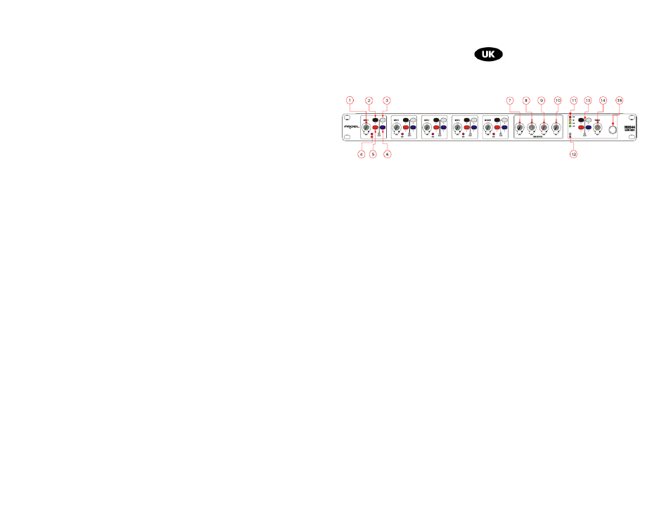
fig.1
1. INPUT1
level
2. Selection INPUT1 to ZONE A
3. Selection INPUT1 to ZONE B
4. Peak level led INPUT1
5. Selection INPUT1 to ZONE C
6. Selection INPUT1 to ZONE D
3. INPUT 2 – 4 and MIC INPUT controls are the same.
7. Output level ZONE A
8. Output level ZONE B
9. Output level ZONE C
10. Output level ZONE D
11. Bar led level monitoring meter
12. Power ON LED
13. ZONE monitor ing select ion
14. Headphone level
15. Headphone output
Advertising