Greenheck PCO20000F0 (Lonworks Interface Board) Manuale d'uso
Pagina 2
GB
Connessione alla rete LonWorks
®
:
La connessione alla rete LonWorks
®
si ottiene tramite il connettore a morsetti
estraibili presente sulla scheda (vedi Fig. 5):
1.
connettore verso pCO
2
/pCO
1
;
2.
morsettiera verso rete LonWorks
®
(GND, A, B);
3.
service pin;
4.
LED verde di service;
5.
LED rosso di anomalia.
Per attivare il service pin è sufficiente cortocircuitare per un istante i due pin con la
punta di un cacciavite o simile. Tale attivazione è confermata dall’accensione del
LED di service.
Il LED di service:
•
segnala lo stato del nodo come da protocollo LonWorks
®
;
•
rimane acceso durante l’attivazione del service pin;
•
rimane acceso per un secondo in caso di ricezione di un comando WINK da rete.
Il LED di anomalia segnala l’impossibilità di connessione lato pCO
2
/pCO
1
. In caso
di accensione del LED rosso di anomalia, verificare che il baud rate della
comunicazione seriale sul pCO
2
/pCO
1
sia impostato a 4800.
La connessione fisica alla rete LonWorks
®
deve essere eseguita come da
indicazioni e specifiche LonWorks
®
.
Per ulteriori informazioni relative all’installazione, alla manutenzione, alla sezione
ed al tipo di cavo si rimanda alla letteratura LonWorks
®
.
Caratteristiche tecniche
Condizioni di funzionamento: 0T65 °C; 20÷80 % U.R. non condensante;
Condizioni di immagazzinamento: -20T70 °C; 20÷80 % U.R. non condensante;
Grado di inquinamento ambientale: normale;
Dimensioni (mm): 60x30x20, (60x30: basetta, 20: larghezza componenti fuori tutto).
Avvertenze. Precauzioni nel maneggiare la scheda.
I danneggiamenti elettrici che si verificano sui componenti elettronici avvengono
quasi sempre a causa delle scariche elettrostatiche indotte dall’operatore.
È quindi necessario prendere adeguati accorgimenti per queste categorie di
componenti, ed in particolare:
• prima di maneggiare qualsiasi componente elettronico o scheda, toccare
una messa a terra (il fatto stesso di evitare di toccare un componente non
è sufficiente in quanto una scarica di 10 000 V, tensione molto facile da
raggiungere con l’elettricità statica, innesca un arco di circa 1 cm);
• i materiali devono rimanere per quanto possibile all’interno delle loro
confezioni originali. Se necessario, prelevare la scheda da una confezione
e trasferire il prodotto in un imballo antistatico senza toccare entrambi i lati
della scheda con le mani;
• evitare nel modo più assoluto di utilizzare sacchetti in plastica, polistirolo
o spugne non antistatiche;
• evitare nel modo più assoluto il passaggio diretto tra operatori (per evitare
fenomeni di induzione elettrostatica e conseguenti scariche).
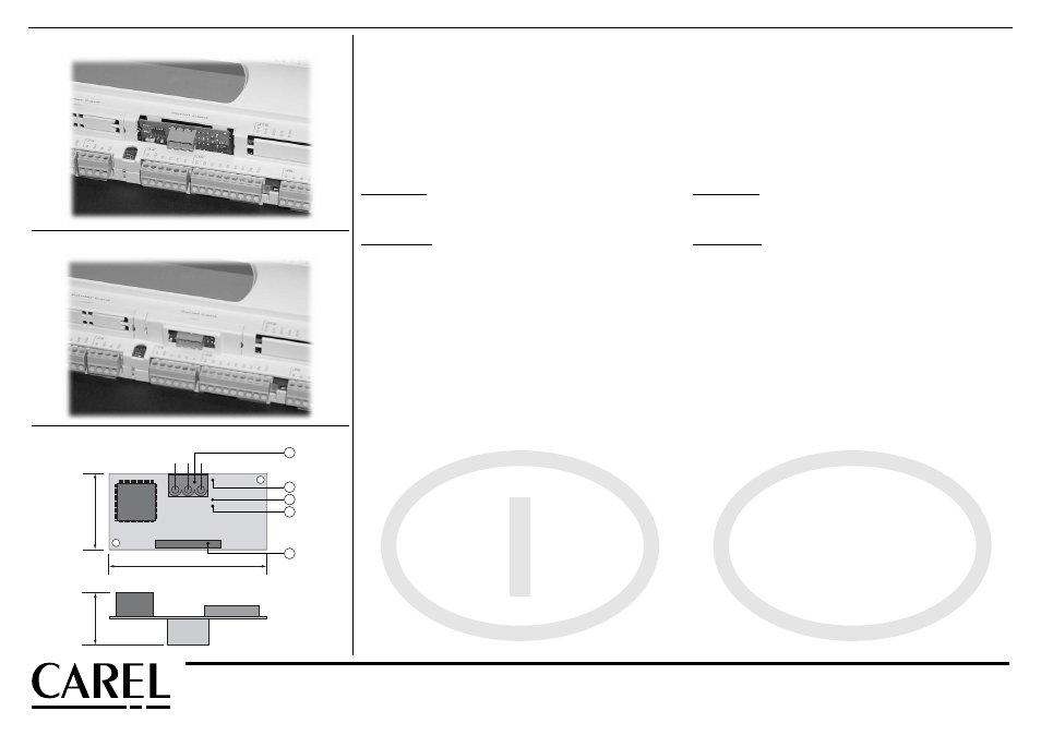
Connection to the LonWorks
®
network:
The connection to the LonWorks
®
network is performed using the removable
terminal connector present on the board (see Fig. 5):
1.
connector to pCO
2
/pCO
1
;
2.
terminal block for LonWorks
®
network (GND, A, B);
3.
service pin;
4.
service green LED;
5.
anomaly red LED.
To activate the service pin, simply short-circuit the two pins for an instant using the
tip of a screwdriver or similar. The activation is
confirmed
by the lighting of the service
LED.
The service LED:
•
signals the status of the node, as per the LonWorks
®
protocol;
•
remains ON during the activation of the service pin;
•
remains ON for a second when receiving a WINK command from the network.
The anomaly LED signals the impossibility of connection on the pCO
2
/pCO
1
side. If
the red anomaly LED is ligthed, check the baud rate of the serial communication
on pCO
2
/pCO
1
is set at 4800.
The real connection to the LonWorks
®
network must be performed following the
LonWorks
®
instructions and specifications.
For further information on installation, maintenance, cross-section and type of
cable, please refer to LonWorks
®
documentation.
Technical specifications
Operating conditions: 0T65°C; 20÷80%rH non-condensing;
Storage conditions: -20T70°C; 20÷80%rH non-condensing;
Environmental pollution: normal;
Dimensions (mm): 60x30x20, (60x30: base, 20: overall component width).
Warnings. Precautions for handling the board.
The electrical damages on the electronic components usually occurs because of
electrostatic discharges caused by the operator.
Therefore, when handling these components, you must take the following
precautions:
• before handling any electronic component or card, touch a grounding (not
touching it, is not sufficient, because a 10.000V discharge, a very easy voltage
value to reach with static electricity, produces an electric arc of about 1cm);
• the components must be kept inside their original package as long as
possible. If necessary, take the main board from a package and put it into
an antistatic package without touching both sides of the board with your hands;
• absolutely avoid non-antistatic plastic bags or spongee and polystyrene;
• absolutely avoid the handing over of a card from one operator to another (to
avoid any electrostatic induction and discharges).
CAREL S.p.A.
Via dell’Industria, 11 - 35020 Brugine - Padova (Italy)
Tel. (+39) 0499716611 – Fax (+39) 0499716600
http://www.carel.com – e-mail: [email protected]
Carel si riserva la possibilità di apportare modifiche o cambiamenti ai propri prodotti senza alcun preavviso.
Carel reserves the right to modify the features of its products without prior notice.
cod. +050004040 rel. 3.0 - 24.02.03
Fig. 3
Fig. 4
60
29
20
GND A
B
1
5
4
3
2
Fig. 5
Inserimento scheda/Insert hatch
Chiusura dello sportellino/Close hatch
Dimensioni (mm)/Dimensions (mm)