Multi-Contact MA260 Manuale d'uso
Pagina 4
Advanced Contact Technology
4 / 8
www.multi-contact.com
10
L= 6 - 7,5mm
S
max. 1 mm
12
9
A
A
11
Montaggio
Assembly
Preparazioni dei cavi
Cable preparation
Possono essere collegati cavi con
costruzione di classe 5 o 6.
Cables with a strand construction of
classes 5 and 6 can be connected.
Avvertenza:
Non utilizzare conduttori non
protetti o già ossidati. Si consiglia di
utilizzare i conduttori stagnati. Tutti
i cavi solari MC hanno conduttori
stagnati di alta qualità.
Note:
Use no uncoated or already
oxidised conductors. It is advantage
to use tinned conductors. All MC
solar cables have high-quality, tinned
conductors.
(ill. 9)
Possono essere connessi cavi con
sezione conduttore compresa tra 2.5 –
4mm² corrispondente a 14 – 10 AWG.
Attenzione
I pin o le boccole di test devono
corrispondere al relativo diametro
del cavo (A).
Tipo: A = Ø del pressacavo
PV-K...T4/...6I:
3 – 6 mm
PV-K...T4/...6II:
5.5 – 9 mm
(ill. 9)
Cables with conductor cross section
from 2,5 - 4mm² resp. from 14 - 10
AWG can be connected.
Attention
Take care that the type of test
plug or test socket matches the
cable diameter (A).
Type: A = Ø range of cable
PV-K...T4/...6I:
3 – 6 mm
PV-K...T4/...6II:
5.5 – 9 mm
(ill. 10)
Spellare il cavo.
Rimuovere da 6,0 a 7,5 mm di isola-
mento dalla parte terminale del cavo
Attenzione:
Prestare attenzione a non tagliare
i trefoli.
Avvertenza:
Per indicazioni sull’uso della
pinza per crimpare PV-AZM e sulla
sostituzione dei kit di lame, consultare
le istruzioni d’uso di MA267 at www.
multi-contact.com
(ill. 10)
Strip cable insulation
1)
Remove 6 to 7,5 mm of insulation
from the end of the cable.
Attention
Take care not to cut individual
strands.
1)
For directions on the operation of strip-
ping pliers PV-AZM... and changing blade
sets, see operating instruction MA267 at
www.multi-contact.com
Crimpatura
Crimping
Importante
Utilizzare esclusivamento l‘inserto
di crimpatura MC3 PV-ES-
CZM-16100!
Important
Use only the MC3 crimp insert
PV-ES-CZM-16100!
(ill. 11)
1. Inserire la parte metallica del con-
nettore femmina o maschio nella
guida per la sezione appropriata.
2. Inserire il cavo nella bussola di
crimpatura fi no in fondo e fi ssar-
lo. Mantenere il cavo in posizione
all’interno della bussola.
(ill. 11)
1. Place the metal part of the female
or male coupler in the guide for the
appropriate cross section.
2. Insert the wire into the crimping
sleeve as far as it will go. Hold the
wire in place in the sleeve.
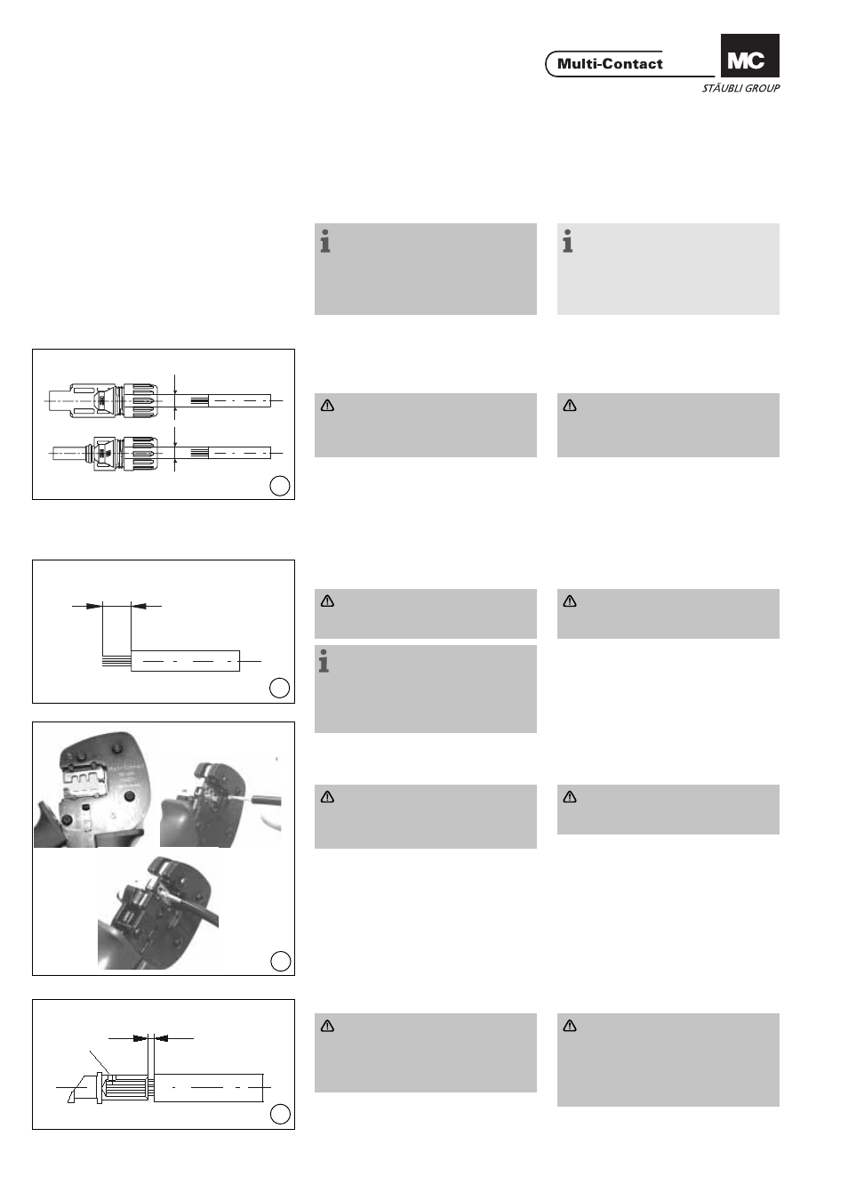
(ill. 12)
Attenzione:
I trefoli devono essere visibili
attraverso il foro S e la distanza
massima di 1mm non deve esse-
re superata esternamente.
3. Serrare completamente la pinza per
crimpare.
(ill. 12)
Attention
All strands of the wires must be
correctly inserted into the bore-
hole and visible in sight hole S.
The max. distance of 1mm must
not be exceeded.
3. Completely close the crimping tool.