Ethernet / profinet interbus profibus – Multi-Contact MA213-04 Manuale d'uso
Pagina 4
Advanced Contact Technology
4 / 8
www.multi-contact.com
B
S
Ethernet / Profinet
Interbus
Profibus
7
6
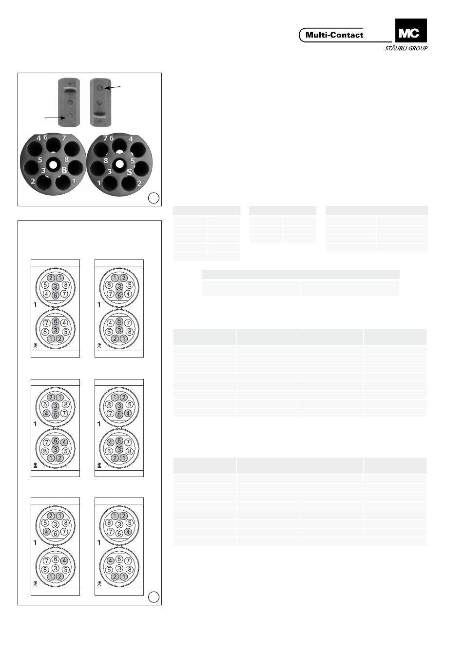
Assemblaggio dei contatti
negli inserti
Contact assembly in inserts
(ill. 6)
L‘inserto femmina è marchiato con
una B, quello maschio con una S. Il
numero dei contatti è sul lato posterio-
re� I contatti vengono inseriti dal lato
posteriore�
(ill. 6)
The female insert is marked with a B,
the pin insert is marked with an S� The
contact numbers are on the back side�
The contacts will be inserted from
back side�
Disposizione dei contatti nel
porta contatti
Contact arrangement of the
contact carrier
(ill. 7)
(Visto dal lato connessione)
(ill. 7)
(Seen from the termination side)
Configurazione con 4 doppini
T568A
Configuration with 4 pairs T568A
Configurazione con 4 doppini
T568B
Configuration with 4 pairs T568B
Lato maschio
Lato femmina
Pin side
Socket side
Interbus
DO
1
/DO
2
DI
3
/DI
6
COM
4
Profibus
Line A
1
Line B
2
GND
4
Ethernet & Profinet
TX+
1
TX-
2
RX+
3
RX-
6
CANbus
Configurazione singola secondo
le specifiche del BUS
Individual configuration accor-
ding to BUS specifications
No. contatto
Contact No.
No. doppino
Pair No.
Colore
Colour
1
1
Bianco/Verde
white/green
2
1
Verde
green
3
2
Bianco/Arancio
white/orange
4
3
Blu
blue
5
3
Bianco/Blu
white/blue
6
2
Arancio
orange
7
4
Bianco/Marrone
white/brown
8
4
Marrone
brown
Tab. 2
Tab. 3
No. contatto
Contact No.
No. doppino
Pair No.
Colore
Colour
1
1
Bianco/Arancio
white/orange
2
1
Arancio
orange
3
2
Bianco/Verde
white/green
4
3
Blu
blue
5
3
Bianco/Blu
white/blue
6
2
Verde
green
7
4
Bianco/Marrone
white/brown
8
4
Marrone
brown