A fi lo fl ush, Montaggio del cavo cable assembly, Controllo del montaggio checking of assembly – Multi-Contact MA213-03 Manuale d'uso
Pagina 4: Smontaggio dei contatti extraction of contacts
Advanced Contact Technology
4 / 4
www.multi-contact.com
8
LW L-B
LW L-S
3
2
1
3
2
1
9
10
4.
2
21
11
12
POF-B
POF-S
MC
MC
POF-B
POF-S
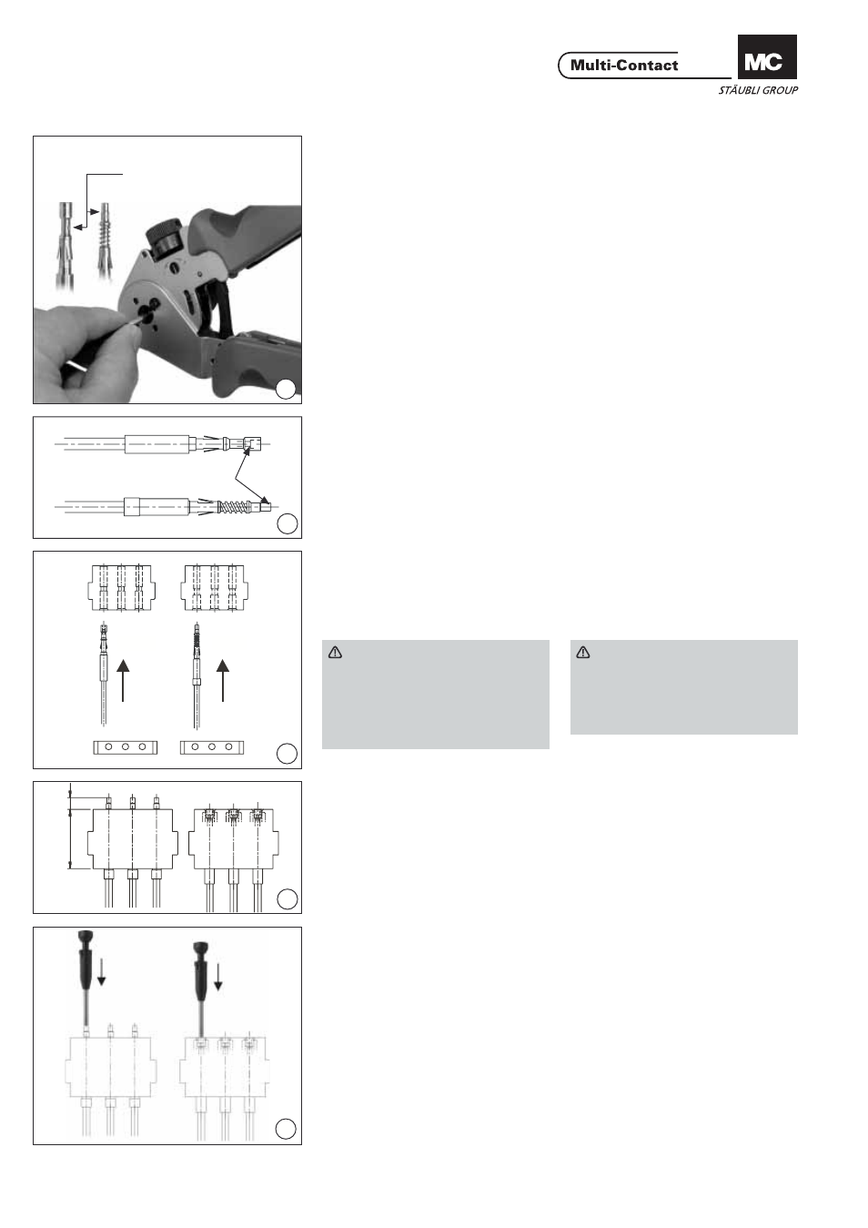
Montaggio del cavo
Cable assembly
(ill. 8)
Per crimpare si vedano anche le istru-
zioni operative della pinza di crimpa-
tura MA065. Inserire il contatto per
le POF nella zona di crimpature fi no
allo stop e chiudere la pinza fi no alla
prima posizione di blocco. Inserire il
cavo preparato nel contatto POF fi no
alo stop, spingere leggera pressione il
cavo e il contatto e chiudere la pinza
completamente. Dopo il crimpaggio
pinza si deve aprire atutomaticamente.
Questo garantisce che la crimpature è
stata eseguita correttamente.
(ill. 8)
For crimping see the operating
instructions of the crimping pliers
MA065 (www.multi-contact.com)
Insert the POF contact into the crimp
place up to the stop and close the
crimp pliers up to the fi rst snap-in
position.
Insert the prepared cable into the POF
contact up to the stop, gently push in
the cable and the contact and close
the pliers completely. After crimping
the pliers must open automaticaly.
This ensures that the crimp procedure
has been correctly executed.
(ill. 9)
Controllare: i cavi devono essere a fi lo
della superfi cie frontale del contatto.
(ill. 9)
Check: The cables must be fl ush (see
arrow) with the front side.
(ill. 10)
Inserire manualmente i contatti dal
lato posteriore del porta contatti fi no
all’innesto. (Il lato posteriore è quello
senza logo MC).
(ill. 10)
Manually insert the contacts into the
contact carriers from the back until
they engage. (The back is the side
without “MC” logos).
Attenzione
Maschi e femmina hanno porta
contatti diversi, contrassegnati
dalle sigle POF-S per i maschi
e POF-B per le femmine. Tirare
il cavo per verifi carne il corretto
inserimento.
Achtung
Plugs and sockets have different
contact carriers. POF-S for pins,
POF-B for sockets.
Check correct engagement by
pulling the cable.
Controllo del montaggio
Checking of assembly
(ill. 11)
Il corretto inserimento dei contatti si
deve verifi care sulla misura di con-
trollo di 4,2mm (per i maschi). Le
femmine devono corrispondere al fi lo
superiore del porta contatti.
(ill. 11)
The correct engagement of the
contacts must be checked with the
dimension 4.2mm (for pins). The sock-
ets must be fl ush with the top edge of
the contact carrier.
Smontaggio dei contatti
Extraction of contacts
(ill. 12)
Introdurre l’attrezzo di smontaggio dal
lato di connessione fi no all’arresto e
staccare i contatti dal porta contatti
esercitando una trazione.
(ill. 12)
Insert extraction tool into the contact
carrier from the plugging side as far as
it will go and pull out the contacts.
Punto di crimpaggio
Crimp position
a fi lo
fl ush
© b
y
Multi-Contact A
G, Switz
erland – MA213-03 – 06.2012, Inde
x d
, Global Communications – Änderungen v
orbehalten / Subject to alterations