Proel UHFSPLITAL Manuale d'uso
Pagina 15
15
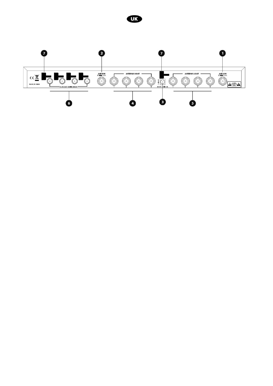
Rear Panel:
pict.2
1. Antenna A input connector
2. Antenna B input connector
3. Mains
socket
4. TNC female output connectors. They distribute the signal received to the antenna B input sockets of the
receivers.
5. TNC female output connectors. They distribute the signal received to the antenna A input sockets of the
receivers.
6. Four 12VCD outputs for direct power supplying of the 4 wireless receivers
4. INSTALLATION
• Connect the two antennas of one of 4 connected receivers to the 2 inputs A and B (pict.2 ref.1,2)
• Connect the antenna A and B inputs (pict.2 rif.4,5) of the receivers to the A and B outputs of the splitter (pict.3).
Note:To ensure optimum performance of the unit, keep it away from humidity or water. This antenna booster kit
provides enhanced S/N ratio for better reception and longer distance transmission.
• After connecting the antennas, connect the AC/DC adapter to the UHF Splitter (fig.2 rif.3) and to the mains outlet.
• Connect receivers' input supply to 12Vdc outputs ( pict.2 ref.3)
• Switch the unit ON, the Power LED will light up and the unit is ready for use.
Note: For short distances (10/15 mt.) a 50Ω RG58-type coaxial cable can be used, while RG213U or higher
feature cables are recommended for longer distances.